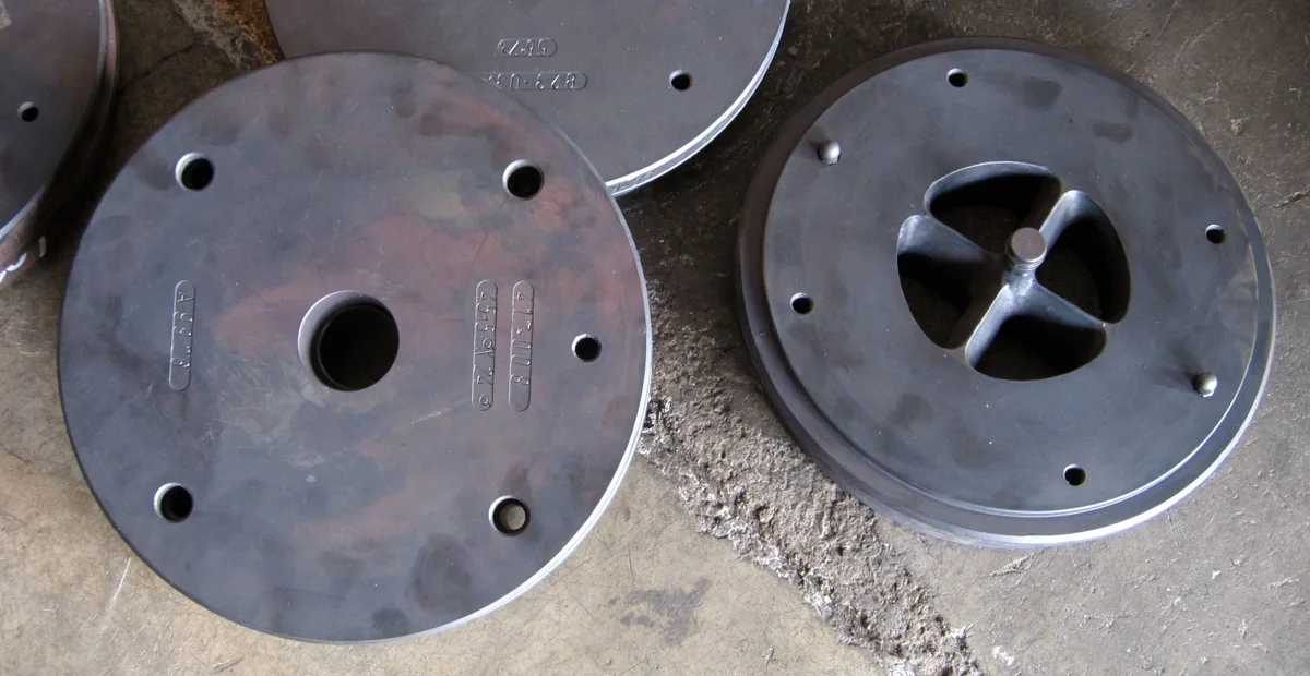
Every extruded aluminium round tube is defined by its die: the outside diameter comes from the die aperture and the wall from the gap between the die and a mandrel. Choosing a diameter and wall that the industry already has tooling for avoids a die charge and a trial run, while a non-standard size means designing a new die. This guide explains porthole and seamless tube dies, gives metric and inch size charts with calculated weights, and shows how alloy, tolerance and press size decide what can be made.
What a round tube die is, and why the size you pick matters
A round tube die is a set of hardened hot-work tool steel parts, almost always H13 (1.2344) or a premium variant of it, that shapes a heated aluminium billet into a hollow circular section. Unlike a solid bar die, a tube die has two working surfaces: the outer die cap that sets the outside diameter (OD) and an inner mandrel that sets the inside diameter (ID). The gap between them is the wall thickness, and the accuracy of that gap, all the way round, decides whether the tube comes out concentric.
Because both diameter and wall are fixed by the tooling, every combination needs its own die. A Ø50 × 3 mm tube and a Ø50 × 4 mm tube are two different tools, and so are Ø50.8 mm (2 in) and Ø50 mm. Buyers who are new to extrusion often assume tube is cut from a continuous range, the way sheet is cut from coil; in reality the available sizes are a library of discrete dies built up over decades by extruders around the world.
That has a direct commercial consequence. When the OD and wall on your drawing match a die that already exists, production can start from proven tooling, with known straightness and tolerance behaviour and no tooling invoice. When they do not, a new die must be designed, machined, heat-treated, nitrided and trialled, and the first trial often needs correction before the tube is accepted. For small and medium orders, the die cost and the trial time can outweigh the metal cost, which is why it pays to check a standard size chart before freezing a design.
Tooling is only half the story. The same die can run several alloys, but not all of them equally well, and some alloys are better made as seamless tube on a different type of press. Tolerance class, temper, surface finish and length also influence which route is used. The sections below take each of these in turn.
Tooling types
Porthole, bridge and die-and-mandrel tooling compared
Hollow aluminium tube is extruded by two fundamentally different methods. Which one is used depends on the alloy, the size, the end use and the specification on the purchase order.
Porthole die
The most common tube die. The billet is split by the bridges of a mandrel assembly into several streams that pass through ports, flow around the mandrel and weld back together in a welding chamber under high pressure before leaving the die. A solid billet is used, so standard presses can run it.
Bridge and spider dies
Variants of the same principle. In a bridge die the mandrel is supported by a bridge across the die; in a spider die by radial arms. Large-diameter tubes often use bridge-type tooling. All of them produce longitudinal seam welds where the streams rejoin.
Die-and-mandrel (seamless)
A hollow billet, cast hollow or pierced, is pushed over a mandrel that sits in the die aperture. The metal never separates, so there is no seam weld. This method needs a press with a piercing or mandrel system and is used for seamless tube and pipe.
Multi-cavity dies
Small tubes are often extruded through dies with two, four or more openings at once. This raises output and is one reason small standard sizes are economical; it also means small new sizes may be designed as multi-cavity tools.
Drawing dies and plugs
Cold drawing is a separate step after extrusion. The tube is pulled through a carbide or hardened steel die over a plug or mandrel to reduce OD and wall, tighten tolerances and improve the surface. Drawing tooling is much cheaper than an extrusion die.
Feeder and step dies
A feeder plate in front of the die controls metal flow and can allow a slightly larger tube than the container would otherwise permit. Step dies change section along the length and are a specialist product, not a stock item.
2024, 7075, 5083, 5086, 6061, 6082, 3003 and others
Typical specifications
EN 755-8, ASTM B221 / B429 (structural)
EN 755-7, ASTM B241, ASTM B210 (drawn), AMS specifications
Wall concentricity
Good; set by die design and mandrel deflection
Very good on modern presses; depends on mandrel alignment
Relative cost
Lower; standard presses, high output
Higher; special presses and hollow billets
Where it is preferred
Frames, handrails, furniture, structures, general engineering
Pressure lines, hydroformed parts, aerospace, high-stress or cryogenic service
The seam welds in porthole tube are solid-state bonds formed by pressure and temperature, not fusion welds. In 6xxx alloys made with a well-designed die, they are sound and the tube meets the same tensile minimums as seamless material in most structural uses. Problems arise when the welding chamber pressure is too low, when the alloy is hard to bond (2xxx, high-strength 7xxx and high-magnesium 5xxx), or when the tube is later expanded, flared or hydroformed, which concentrates strain at the seams. That is why many specifications for pressure pipe and hydroformed parts require seamless tube, and why the purchase order should say so explicitly.
How dies are made
How a new round tube die is made, and what limits the size
DesignThe die designer sets the number of ports, the bridge shape, the welding chamber height and the bearing lengths so that metal reaches the die gap at even speed all round. Uneven flow is what causes eccentric walls, wavy tube and poor seam welds.
MachiningThe mandrel and cap are rough-machined from H13 bar, heat-treated to high hardness, then finish-machined and spark-eroded (EDM) to final dimensions. Bearing surfaces are polished.
NitridingThe working surfaces are nitrided to give a hard, wear-resistant case. Dies are re-nitrided periodically during their life.
TrialThe die is run on the press with production alloy. The first tube is measured for OD, wall at several points, ovality and straightness, and sectioned to check the seam welds.
CorrectionIf the wall is uneven or the tube bows, the die maker adjusts bearings or flow paths and the die is trialled again. Simple round tubes usually settle quickly; very thin walls and large diameters take more correction.
Production and maintenanceThe die is cleaned in caustic soda after each run, inspected, re-nitrided when needed and stored for repeat orders. Wear gradually enlarges the bearings, and the die is retired when it can no longer hold tolerance.
Die life varies with alloy, section and press practice, so it is quoted as an estimate rather than a fixed number. Soft alloys such as 6063 are kind to tooling; 6082, 6061 and 7xxx alloys are harder on bearings; thick walls with low extrusion ratios are easier than thin walls on large diameters.
What can be extruded is limited by the press. The OD must fit within the die diameter the press accepts, and the force needed rises with the cross-sectional reduction and the alloy's flow stress. Very large tubes, above about 300 mm OD, are made on large presses with big containers or by spreading techniques, and the range of available wall thicknesses narrows. At the other extreme, very small diameters below about 8 – 10 mm are often extruded slightly oversize and cold drawn to final dimension.
Wall-to-OD ratio
Very thin walls on a large diameter are hard to fill evenly and tend to go oval; very thick walls on a small diameter leave little room for a strong mandrel. Mid-range ratios run fastest and most consistently.
Minimum wall
For soft 6xxx alloys on small tubes, walls around 0.8 – 1 mm are practical by extrusion; thinner walls are normally achieved by cold drawing. Harder alloys need thicker minimum walls.
Mandrel strength
The mandrel is supported only by its bridges or by the press mandrel bar, so it deflects under load. That deflection is the main cause of wall eccentricity and the reason why designers keep bridges sturdy.
Extrusion ratio
If the reduction from container to tube is too small, the metal is under-worked and seam welds may be weak; if it is too large, pressure rises and speed falls. Extruders choose the press size to keep the ratio workable.
Length
Tube is typically cut to 3 m, 6 m or similar lengths at the press; longer lengths depend on the run-out table and stretcher. Coiled tube is a different product covered by its own standard.
Alloy behaviour
A die designed for 6063 may need different bearings for 6082 or 7075, so stating the alloy at the enquiry stage avoids surprises in trial.
The table lists metric outside diameter and wall combinations that are widely produced across the extrusion industry. For each size we give the inside diameter and the theoretical weight, calculated from a density of 2.70 g/cm³ (accurate within about 1 % for 6060, 6063, 6061 and 6082). For 2024 multiply by about 1.03, for 7075 by about 1.04 and for 5083 by about 0.99. Sizes are written OD × wall in millimetres.
Size (mm)
ID (mm)
kg per metre
lb per foot
Ø6 × 1
4
0.042
0.028
Ø8 × 1
6
0.059
0.040
Ø8 × 1.5
5
0.083
0.056
Ø10 × 1
8
0.076
0.051
Ø10 × 1.5
7
0.108
0.073
Ø10 × 2
6
0.136
0.091
Ø12 × 1
10
0.093
0.063
Ø12 × 1.5
9
0.134
0.090
Ø12 × 2
8
0.170
0.114
Ø14 × 1
12
0.110
0.074
Ø14 × 2
10
0.204
0.137
Ø15 × 1
13
0.119
0.080
Ø15 × 1.5
12
0.172
0.115
Ø15 × 2
11
0.221
0.148
Ø15 × 3
9
0.305
0.205
Ø16 × 1
14
0.127
0.085
Ø16 × 1.5
13
0.184
0.124
Ø16 × 2
12
0.238
0.160
Ø16 × 3
10
0.331
0.222
Ø18 × 1
16
0.144
0.097
Ø18 × 1.5
15
0.210
0.141
Ø18 × 2
14
0.271
0.182
Ø18 × 3
12
0.382
0.256
Ø20 × 1
18
0.161
0.108
Ø20 × 1.5
17
0.235
0.158
Ø20 × 2
16
0.305
0.205
Ø20 × 3
14
0.433
0.291
Ø20 × 4
12
0.543
0.365
Ø20 × 5
10
0.636
0.427
Ø22 × 1
20
0.178
0.120
Ø22 × 1.5
19
0.261
0.175
Ø22 × 2
18
0.339
0.228
Ø22 × 3
16
0.483
0.325
Ø25 × 1
23
0.204
0.137
Ø25 × 1.5
22
0.299
0.201
Ø25 × 2
21
0.390
0.262
Ø25 × 2.5
20
0.477
0.321
Ø25 × 3
19
0.560
0.376
Ø25 × 4
17
0.713
0.479
Ø25 × 5
15
0.848
0.570
Ø28 × 1.5
25
0.337
0.227
Ø28 × 2
24
0.441
0.296
Ø28 × 3
22
0.636
0.427
Ø30 × 1.5
27
0.363
0.244
Ø30 × 2
26
0.475
0.319
Ø30 × 2.5
25
0.583
0.392
Ø30 × 3
24
0.687
0.462
Ø30 × 4
22
0.882
0.593
Ø30 × 5
20
1.060
0.712
Ø32 × 1.5
29
0.388
0.261
Ø32 × 2
28
0.509
0.342
Ø32 × 3
26
0.738
0.496
Ø32 × 4
24
0.950
0.638
Ø32 × 5
22
1.145
0.769
Size (mm)
ID (mm)
kg per metre
lb per foot
Ø35 × 1.5
32
0.426
0.286
Ø35 × 2
31
0.560
0.376
Ø35 × 3
29
0.814
0.547
Ø35 × 4
27
1.052
0.707
Ø35 × 5
25
1.272
0.855
Ø38 × 1.5
35
0.464
0.312
Ø38 × 2
34
0.611
0.410
Ø38 × 3
32
0.891
0.598
Ø38 × 4
30
1.154
0.775
Ø40 × 1.5
37
0.490
0.329
Ø40 × 2
36
0.645
0.433
Ø40 × 2.5
35
0.795
0.534
Ø40 × 3
34
0.942
0.633
Ø40 × 4
32
1.221
0.821
Ø40 × 5
30
1.484
0.997
Ø40 × 6
28
1.730
1.163
Ø40 × 8
24
2.171
1.459
Ø42 × 2
38
0.679
0.456
Ø42 × 3
36
0.992
0.667
Ø42 × 4
34
1.289
0.866
Ø45 × 2
41
0.729
0.490
Ø45 × 3
39
1.069
0.718
Ø45 × 4
37
1.391
0.935
Ø45 × 5
35
1.696
1.140
Ø50 × 1.5
47
0.617
0.415
Ø50 × 2
46
0.814
0.547
Ø50 × 2.5
45
1.007
0.677
Ø50 × 3
44
1.196
0.804
Ø50 × 4
42
1.561
1.049
Ø50 × 5
40
1.909
1.282
Ø50 × 6
38
2.239
1.505
Ø50 × 8
34
2.850
1.915
Ø50 × 10
30
3.393
2.280
Ø55 × 2
51
0.899
0.604
Ø55 × 3
49
1.323
0.889
Ø55 × 5
45
2.121
1.425
Ø60 × 2
56
0.984
0.661
Ø60 × 2.5
55
1.219
0.819
Ø60 × 3
54
1.450
0.975
Ø60 × 4
52
1.900
1.277
Ø60 × 5
50
2.333
1.567
Ø60 × 6
48
2.748
1.847
Ø60 × 8
44
3.529
2.371
Ø60 × 10
40
4.241
2.850
Ø63 × 2
59
1.035
0.695
Ø63 × 3
57
1.527
1.026
Ø63 × 5
53
2.460
1.653
Ø65 × 2
61
1.069
0.718
Ø65 × 3
59
1.578
1.060
Ø65 × 5
55
2.545
1.710
Ø65 × 10
45
4.665
3.135
Ø70 × 2
66
1.154
0.775
Ø70 × 3
64
1.705
1.146
Ø70 × 4
62
2.239
1.505
Ø70 × 5
60
2.757
1.852
Ø70 × 6
58
3.257
2.189
Ø70 × 10
50
5.089
3.420
Ø75 × 2
71
1.238
0.832
Ø75 × 3
69
1.832
1.231
Ø75 × 4
67
2.409
1.619
Ø75 × 5
65
2.969
1.995
Ø75 × 10
55
5.513
3.705
Ø80 × 2
76
1.323
0.889
Ø80 × 3
74
1.959
1.317
Ø80 × 4
72
2.579
1.733
Ø80 × 5
70
3.181
2.137
Ø80 × 6
68
3.766
2.531
Ø80 × 8
64
4.886
3.283
Ø80 × 10
60
5.938
3.990
Ø80 × 15
50
8.270
5.557
Ø85 × 3
79
2.087
1.402
Ø85 × 5
75
3.393
2.280
Ø90 × 3
84
2.214
1.488
Ø90 × 4
82
2.918
1.961
Ø90 × 5
80
3.605
2.422
Ø90 × 10
70
6.786
4.560
Size (mm)
ID (mm)
kg per metre
lb per foot
Ø100 × 2
96
1.663
1.117
Ø100 × 3
94
2.468
1.659
Ø100 × 4
92
3.257
2.189
Ø100 × 5
90
4.029
2.707
Ø100 × 6
88
4.784
3.215
Ø100 × 8
84
6.243
4.195
Ø100 × 10
80
7.634
5.130
Ø100 × 15
70
10.815
7.267
Ø100 × 20
60
13.572
9.120
Ø110 × 3
104
2.723
1.830
Ø110 × 5
100
4.453
2.992
Ø110 × 10
90
8.482
5.700
Ø120 × 3
114
2.977
2.001
Ø120 × 4
112
3.936
2.645
Ø120 × 5
110
4.877
3.277
Ø120 × 6
108
5.802
3.899
Ø120 × 8
104
7.600
5.107
Ø120 × 10
100
9.331
6.270
Ø120 × 15
90
13.360
8.977
Ø120 × 20
80
16.965
11.400
Ø125 × 5
115
5.089
3.420
Ø125 × 10
105
9.755
6.555
Ø130 × 5
120
5.301
3.562
Ø130 × 10
110
10.179
6.840
Ø130 × 15
100
14.632
9.832
Ø140 × 5
130
5.726
3.847
Ø140 × 10
120
11.027
7.410
Ø140 × 20
100
20.358
13.680
Ø150 × 3
144
3.741
2.514
Ø150 × 5
140
6.150
4.132
Ø150 × 6
138
7.329
4.925
Ø150 × 8
134
9.636
6.475
Ø150 × 10
130
11.875
7.980
Ø150 × 15
120
17.177
11.542
Ø150 × 20
110
22.054
14.820
Ø150 × 25
100
26.507
17.812
Ø160 × 5
150
6.574
4.417
Ø160 × 10
140
12.723
8.550
Ø160 × 20
120
23.750
15.960
Ø180 × 5
170
7.422
4.987
Ø180 × 10
160
14.420
9.690
Ø180 × 15
150
20.994
14.107
Ø180 × 20
140
27.143
18.240
Ø200 × 5
190
8.270
5.557
Ø200 × 8
184
13.029
8.755
Ø200 × 10
180
16.116
10.830
Ø200 × 15
170
23.538
15.817
Ø200 × 20
160
30.536
20.519
Ø200 × 25
150
37.110
24.937
Ø200 × 30
140
43.260
29.069
Ø220 × 10
200
17.813
11.970
Ø220 × 20
180
33.929
22.799
Ø250 × 8
234
16.422
11.035
Ø250 × 10
230
20.358
13.680
Ø250 × 15
220
29.900
20.092
Ø250 × 20
210
39.019
26.219
Ø250 × 25
200
47.713
32.062
Ø250 × 30
190
55.983
37.619
Ø280 × 10
260
22.902
15.390
Ø280 × 20
240
44.108
29.639
Ø300 × 10
280
24.599
16.530
Ø300 × 15
270
36.262
24.367
Ø300 × 20
260
47.501
31.919
Ø300 × 25
250
58.316
39.187
Ø300 × 30
240
68.707
46.169
Ø300 × 40
220
88.216
59.279
Ø300 × 50
200
106.029
71.248
Ø350 × 15
320
42.624
28.642
Ø350 × 20
310
55.983
37.619
Ø350 × 25
300
68.919
46.311
Ø350 × 30
290
81.430
54.719
Ø400 × 20
360
64.465
43.319
Ø400 × 25
350
79.522
53.436
Ø400 × 30
340
94.154
63.268
Ø400 × 40
320
122.145
82.078
Ø400 × 50
300
148.440
99.748
Ø450 × 20
410
72.948
49.019
Ø450 × 30
390
106.877
71.818
Ø450 × 40
370
139.110
93.478
Ø500 × 25
450
100.727
67.686
Ø500 × 40
420
156.074
104.877
Ø500 × 50
400
190.852
128.247
Whether a size runs from existing tooling depends on the alloy, the route (porthole or seamless) and the tolerance required, so confirm with your enquiry. Sizes that fall between those listed can often be reached by cold drawing or machining the next standard tube.
Size chart
Inch (imperial) aluminum round tube sizes and weights
North American and many Middle Eastern drawings specify tube in fractional inches with decimal walls such as 0.035, 0.049, 0.065, 0.083 and 0.125 in, the same gauges used for steel and stainless tube. These sizes are made on inch dies, and substituting the nearest metric tube is rarely acceptable when the tube fits into a fitting, a bearing or a mating part. Weights below use 0.0975 lb/in³.
Size (OD × wall)
Metric (mm)
lb per foot
kg per metre
1/4 in × 0.035
6.35 × 0.89
0.028
0.041
1/4 in × 0.049
6.35 × 1.24
0.036
0.054
1/4 in × 0.065
6.35 × 1.65
0.044
0.066
3/8 in × 0.035
9.52 × 0.89
0.044
0.065
3/8 in × 0.049
9.52 × 1.24
0.059
0.087
3/8 in × 0.065
9.52 × 1.65
0.074
0.110
1/2 in × 0.035
12.70 × 0.89
0.060
0.089
1/2 in × 0.049
12.70 × 1.24
0.081
0.121
1/2 in × 0.065
12.70 × 1.65
0.104
0.155
1/2 in × 0.083
12.70 × 2.11
0.127
0.189
5/8 in × 0.035
15.88 × 0.89
0.076
0.113
5/8 in × 0.049
15.88 × 1.24
0.104
0.154
5/8 in × 0.065
15.88 × 1.65
0.134
0.199
5/8 in × 0.083
15.88 × 2.11
0.165
0.246
3/4 in × 0.035
19.05 × 0.89
0.092
0.137
3/4 in × 0.049
19.05 × 1.24
0.126
0.188
3/4 in × 0.065
19.05 × 1.65
0.164
0.244
3/4 in × 0.083
19.05 × 2.11
0.203
0.303
3/4 in × 0.125
19.05 × 3.17
0.287
0.427
7/8 in × 0.049
22.22 × 1.24
0.149
0.221
7/8 in × 0.065
22.22 × 1.65
0.194
0.288
7/8 in × 0.125
22.22 × 3.17
0.345
0.513
1 in × 0.035
25.40 × 0.89
0.124
0.185
1 in × 0.049
25.40 × 1.24
0.171
0.255
1 in × 0.065
25.40 × 1.65
0.223
0.332
1 in × 0.083
25.40 × 2.11
0.280
0.416
1 in × 0.125
25.40 × 3.17
0.402
0.598
1 in × 0.250
25.40 × 6.35
0.689
1.026
1-1/4 in × 0.049
31.75 × 1.24
0.216
0.322
1-1/4 in × 0.065
31.75 × 1.65
0.283
0.421
1-1/4 in × 0.125
31.75 × 3.17
0.517
0.769
1-1/4 in × 0.250
31.75 × 6.35
0.919
1.367
1-1/2 in × 0.049
38.10 × 1.24
0.261
0.389
1-1/2 in × 0.065
38.10 × 1.65
0.343
0.510
1-1/2 in × 0.083
38.10 × 2.11
0.432
0.643
1-1/2 in × 0.125
38.10 × 3.17
0.632
0.940
1-1/2 in × 0.250
38.10 × 6.35
1.149
1.709
1-3/4 in × 0.065
44.45 × 1.65
0.403
0.599
1-3/4 in × 0.125
44.45 × 3.17
0.747
1.111
1-3/4 in × 0.250
44.45 × 6.35
1.378
2.051
2 in × 0.065
50.80 × 1.65
0.462
0.688
2 in × 0.083
50.80 × 2.11
0.585
0.870
2 in × 0.125
50.80 × 3.17
0.861
1.282
2 in × 0.188
50.80 × 4.78
1.252
1.863
2 in × 0.250
50.80 × 6.35
1.608
2.393
2-1/2 in × 0.065
63.50 × 1.65
0.582
0.866
2-1/2 in × 0.125
63.50 × 3.17
1.091
1.624
2-1/2 in × 0.250
63.50 × 6.35
2.068
3.077
3 in × 0.125
76.20 × 3.17
1.321
1.966
3 in × 0.188
76.20 × 4.78
1.943
2.892
3 in × 0.250
76.20 × 6.35
2.527
3.761
3-1/2 in × 0.125
88.90 × 3.17
1.551
2.308
3-1/2 in × 0.250
88.90 × 6.35
2.986
4.444
4 in × 0.125
101.60 × 3.17
1.780
2.650
4 in × 0.188
101.60 × 4.78
2.634
3.920
4 in × 0.250
101.60 × 6.35
3.446
5.128
4 in × 0.500
101.60 × 12.70
6.432
9.572
5 in × 0.125
127.00 × 3.17
2.240
3.333
5 in × 0.250
127.00 × 6.35
4.365
6.496
5 in × 0.500
127.00 × 12.70
8.270
12.307
6 in × 0.125
152.40 × 3.17
2.699
4.017
6 in × 0.250
152.40 × 6.35
5.284
7.863
6 in × 0.500
152.40 × 12.70
10.108
15.042
8 in × 0.250
203.20 × 6.35
7.122
10.598
8 in × 0.500
203.20 × 12.70
13.784
20.512
Note that aluminium pipe is a different sizing system. Pipe is ordered by nominal pipe size and schedule (for example NPS 2 Schedule 40, which has an OD of 2.375 in and a wall of 0.154 in) to ASTM B241 or B429, whereas tube is ordered by actual OD and wall. If your drawing says "2 in pipe", it does not mean a 2 in OD tube. Our aluminium pipe pressure guide covers pipe schedules and pressure ratings.
Weight formula for round tube
Metric
kg/m = π × (OD − t) × t × 0.0027, with OD and wall t in mm
Imperial
lb/ft = π × (OD − t) × t × 1.17, with OD and wall t in inches
Worked example, metric
Ø50 × 3 mm: π × 47 × 3 × 0.0027 = 1.196 kg/m; a 6 m length weighs about 7.2 kg
Worked example, inch
2 in × 0.125 in: π × 1.875 × 0.125 × 1.17 = 0.861 lb/ft; a 20 ft length weighs about 17.2 lb
Which alloys run through round tube dies, and in which tempers
Most round tube is made from the 6xxx alloys because they flow easily, bond well in the welding chamber of a porthole die and reach good strength after press quenching and ageing. The table shows the usual route and tempers for each alloy family.
Aircraft structures and fittings; high fatigue strength
Typical tensile strengths illustrate the range: 6063-T6 is about 240 MPa, 6061-T6 about 310 MPa, 7005-T6 about 350 MPa and 7075-T6 about 570 MPa (Aluminum Association typical values). Specified minimum values for extruded tube are set by ASTM B221, ASTM B241 and EN 755-2, depend on wall thickness and are what the mill certificate reports. Design to the minimums, not the typical values.
Temper also affects tooling choice indirectly. T5 tube is quenched at the press exit by air or water mist, which suits thin-walled 6063 and 6060. Thick-walled 6061 and 6082 need an intense water quench to reach T6 through the wall, so they may be extruded on lines with water-wave quench or solution heat-treated separately. A tube that must be bent after delivery is often ordered in T4 or O and aged afterwards.
The "51" in T6511 means the tube was stretched about 1 – 3 % after quenching to relieve stress and straighten it, with minor straightening allowed afterwards. Stretched tempers move less when one end or side of the tube is machined.
Tolerances
Standards and tolerances for extruded and drawn round tube
Tolerance tables differ by process, so the standard on the order should match the route. In the European system, porthole and seamless tube have separate parts of EN 755, and drawn tube has its own parts of EN 754. In the American system, ASTM B221 covers extruded tube (including porthole tube), B241 covers seamless extruded tube and pipe, and B210 covers drawn seamless tube; dimensional tolerances for all of them are tabulated in ANSI H35.2.
Product
European standard
ASTM / North American standard
Porthole extruded tube, tolerances
EN 755-8 (OD 8 – 450 mm)
ASTM B221 with ANSI H35.2
Seamless extruded tube, tolerances
EN 755-7 (OD 8 – 450 mm)
ASTM B241 with ANSI H35.2
Cold-drawn tube
EN 754-7 (seamless), EN 754-8 (porthole)
ASTM B210 (drawn seamless), ASTM B483 (drawn, general purpose)
Mechanical properties
EN 755-2 (extruded), EN 754-2 (drawn)
Within each ASTM product standard
Structural pipe and tube
—
ASTM B429 (extruded structural pipe and tube)
Chemical composition
EN 573-3
Aluminum Association registration
Inspection document
EN 10204 3.1
Mill test report / EN 10204 3.1
The standards control OD (both the mean diameter and the diameter at any point, which together limit ovality), wall thickness (mean wall and wall at any point, which limit eccentricity), straightness, length and the squareness of cut ends. Tolerances widen as the diameter grows and are wider for the harder alloy group (2xxx, 5xxx with more than about 3 % Mg, and 7xxx) than for 6060, 6063 and 6082.
Drawn tube is markedly tighter than extruded tube and has a smoother surface, which is why hydraulic cylinders, telescopic tubes, precision sleeves and heat exchanger tubes are usually drawn. If a drawing gives an OD tolerance of a few hundredths of a millimetre, plan for cold drawing or machining rather than asking for it from the extrusion die.
Options
When your size is not standard: drawing, machining or a new die
A size that is not in the charts is not necessarily a new die. There are four realistic routes, and the cheapest depends on quantity and tolerance.
Cold draw from a nearby size
If your OD is slightly smaller than a standard extruded size, or you need a thinner or more accurate wall, a standard tube can be drawn down. This is common for small diameters, heat exchanger tube and precision sleeves.
Machine the critical zone
For fit sections only a short length long, turning or honing a heavier standard tube can be cheaper than a die, especially for low quantities.
Use the nearest standard size
Many designs can accept 40 × 3 instead of 40 × 2.8, or a metric tube instead of an inch one. Asking the question early often removes the tooling cost entirely.
Open a new die
For repeat volume, a dedicated die is usually worth it. The buyer typically pays a one-time die charge; the die is then reserved for repeat orders. Terms for die ownership and any credit against volume are agreed in the quotation.
Secondary processing is often what turns a tube into a usable part. Common operations include precision cut-to-length with deburring and chamfering, CNC bending (single or multi-radius, which is easiest in 6063-T5 or T4 tempers), end forming such as flaring, swaging and expansion, drilling, tapping and slotting to drawing, and MIG, TIG or brazed joints. For porthole tube that will be expanded or flared heavily, discuss the seam position and the forming strain at the enquiry stage.
Finish
What it gives
Notes for tube
Mill finish
As extruded; light die lines normal
Usual for tube that will be machined, welded or painted
Anodising
Clear or coloured oxide film, typically 10 – 25 µm architectural
6063 and 6060 give the most uniform colour; seam lines can show faintly on bright finishes
Hard anodising
Thick, wear-resistant film
Used on 6061 and 7075 sleeves and cylinders
Powder coating
Any RAL colour, good weathering
Architectural tube often specified to Qualicoat or AAMA 2604/2605
Polishing and brushing
Mirror or satin decorative surface
Usually followed by clear anodising
Electrophoretic coating
Thin lacquer over anodising
Metallic-look architectural and furniture tube
Applications
Typical round tube applications and the usual specification
Handrails and balustrades: 6063-T5 or T6 in sizes such as Ø38 × 2, Ø42.4 × 2.5 or Ø50 × 2, anodised or powder coated, made as porthole tube to EN 755-8.
HVAC and heat exchangers: 3003 or 6063 tube around Ø19.05 (3/4 in) or Ø12.7 (1/2 in), often cold drawn to tight OD for brazed joints and expansion into fins.
Fitness, furniture and medical equipment: 6061-T6 or 6063-T6 in Ø25 – 60 mm, with bending, drilling and powder coating.
Bicycle and sports frames: 6061 and 7005 tube, frequently drawn or butted after extrusion to vary the wall along the length.
Structures, scaffolding and trailers: 6082-T6 heavier-wall tube such as Ø48.3 × 4, designed to EN 1999 (Eurocode 9) or the Aluminum Design Manual.
Pressure lines and hydroformed parts: seamless 6061, 6082 or 5083 tube to EN 755-7 or ASTM B241.
Aerospace and defence: seamless 2024, 6061 and 7075 tube to AMS specifications, with ultrasonic inspection where required.
Large-diameter rollers and housings: 6061 or 6082 tube above 200 mm OD for printing rollers, conveyor drums and enclosures, usually machined after extrusion.
Ordering
How to order round tube from Metline
SpecifyAlloy and temper, OD × wall (state metric or inch), length, quantity, finish, and the governing standard (EN 755-7/-8, ASTM B221, B241, B210 or a drawing). Say whether seamless tube is required.
Confirm the toolingWe confirm whether the size runs from a standard die, whether drawing or machining from the nearest size is more economical, or whether a new die is justified.
QuotePrice, tolerance class, certification and delivery terms (EXW, FOB, CIF or DAP) for your destination.
Process and inspectCutting, bending or finishing as ordered; dimensional checks of OD, wall, ovality and straightness; EN 10204 3.1 certificate with chemistry and mechanical results.
Pack and shipEnd caps, film or paper interleaving, bundling with spacers and wooden cases or pallets for sea or air freight worldwide.
Do I pay a die charge for a standard round tube size?
Usually not. Where the OD and wall match tooling that already exists for the alloy and route, the tube is priced on metal, processing and finish only. A die charge applies when a new size needs new tooling; it is quoted separately and agreed before the die is made.
What is the difference between porthole tube and seamless tube?
Porthole tube is extruded from a solid billet through a die that splits and rewelds the metal around a mandrel, leaving longitudinal seam welds. Seamless tube is extruded from a hollow billet over a mandrel, so it has no seams. Seamless tube is specified for pressure service, hydroforming and many aerospace uses; porthole tube is standard for structures, frames and architectural work.
Can a 6063 die be used for 6061 or 6082 tube?
Often, but not always. The aperture defines the size, but bearings and flow paths are tuned for an alloy. Harder alloys need more pressure and may fill the die differently, so the die may need adjustment or a separate tool. Always give the alloy when you ask whether a size is available.
How do I get a tighter tolerance than extrusion gives?
Choose cold-drawn tube (EN 754-7/-8 or ASTM B210), which is drawn through a carbide die over a plug after extrusion, or machine the critical length. Extrusion dies alone cannot reliably hold the few-hundredths tolerances used on hydraulic cylinders or precision sleeves.
What is the largest round tube that can be extruded?
Tubes of several hundred millimetres in diameter are extruded on very large presses, and the EN 755-7/-8 tolerance standards cover diameters up to 450 mm. Above roughly 300 mm the choice of walls and alloys narrows, and tubes are often machined after extrusion. Send the size and we will confirm feasibility.
Who owns a new tube die?
Practice varies. Commonly the buyer pays a one-time die charge and the die is reserved for that buyer's repeat orders, while the extruder stores and maintains it. Ownership, confidentiality and any credit of the die cost against volume should be written into the quotation.
Need a round tube size checked?
Send OD, wall, alloy, temper, tolerance and quantity. We will confirm the nearest standard die, the best route and a delivered price worldwide.