Straightening and cutting
Coils feed roller straighteners and flying cut-off saws or rotary cutters. Soft O temper straightens easily; consistent temper along the coil keeps cut lengths straight.



Aluminium tube coil is small-diameter round tube, usually 4 – 20 mm OD, supplied wound into a coil instead of cut into straight lengths. Made from soft, formable alloys such as 1100, 1050, 3003 and 3103 in O or H111 temper, it is uncoiled, straightened, cut and bent on the customer’s own equipment for refrigerant lines, heat exchangers, gas and oil lines and instrument tubing. This guide covers alloys, standards, sizes, weights and how to specify it.
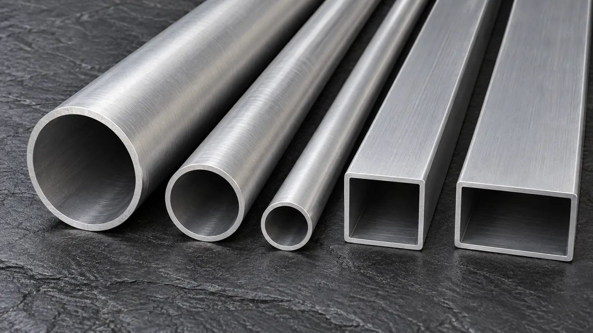
Tube coil is a supply format, not a separate alloy. Long lengths of small round tube, hundreds or thousands of metres in one piece, are wound onto a coil so that a manufacturer can feed them continuously into straightening, cutting and bending machines with very little scrap and no joints.
There are two main routes to make it. Extruded coiled tube is pressed through a die and coiled directly at the press; ASTM B491 covers this product for general-purpose uses such as refrigeration service, gas lines, oil lines and instrument lines, in outside diameters from 6.00 to 20.00 mm (0.250 – 0.750 in). Drawn coiled tube starts as an extruded hollow that is cold-drawn through dies over a mandrel to reach thinner walls and tighter tolerances, then annealed; seamless drawn tube is covered by ASTM B210 and EN 754, and general-purpose drawn tube by ASTM B483.
Aluminium tube coil competes directly with copper coil in air conditioning and refrigeration. It is far lighter (aluminium is about 2.7 g/cm³ against about 8.9 g/cm³ for copper), its price is less volatile, and it removes galvanic corrosion problems where an aluminium fin coil meets a copper tube. The trade-offs are lower strength, which calls for slightly thicker walls, and the need for proper brazing or mechanical joints in place of simple soft soldering.
Coiled tube is almost always made from non-heat-treatable alloys, because the tube has to be soft enough to coil, uncoil and bend. Strength therefore comes from wall thickness and alloy choice rather than heat treatment.
| Alloy | Type | Key features | Typical uses |
|---|---|---|---|
| 1050 / 1060 | 99.5 – 99.6 % Al | Highest conductivity and ductility, lowest strength | Instrument and gas lines, solar and low-pressure heat exchange |
| 1100 | 99.0 % Al, small Cu addition | Very formable, good corrosion resistance, slightly stronger than 1050 | Refrigerant lines, evaporator tube, general fluid lines |
| 1200 / 1235 | Commercially pure | Soft, easy to size and coil; B491 lists sizing after extrusion for 1200-H111 and 1235-H111 | Refrigerant coils, small-bore heat exchanger tubing |
| 3003 | Al-Mn (about 1.2 % Mn) | About 20 % stronger than 1100 with similar formability and corrosion resistance; brazeable | Condenser and evaporator tubes, HVAC line sets, heat pumps |
| 3103 | Al-Mn (EN designation) | European counterpart close to 3003, widely used in EN-market heat exchangers | HVAC, solar thermal, light industrial lines |
| 5052 | Al-Mg (2.5 % Mg) | Higher strength and better seawater resistance; less easy to coil in thick walls | Fuel and hydraulic lines, marine instrumentation |
| 6063 | Al-Mg-Si | Heat-treatable; usually straight lengths, coiled only in soft temper for special forming jobs | Decorative or anodised formed parts |
For most refrigeration and HVAC work the choice is between 1100 and 3003. 3003 gives a useful margin of strength for higher-pressure refrigerants and is common in brazed heat exchangers; 1100 is chosen where maximum bendability or slightly better conductivity matters. See the 3003 tube and 1100 tube pages for full alloy data.
Typical values for annealed (O temper) material from Aluminum Association data. H111 is slightly work-hardened after annealing, from coiling and straightening, and sits just above O. Tube supplied to ASTM B210 or B491 is tested against the minimum and maximum limits in the standard; the mill certificate reports the actual results.
| Alloy and temper | Tensile strength (typ.) | Yield strength (typ.) | Elongation (typ.) | Thermal conductivity |
|---|---|---|---|---|
| 1050-O | 76 MPa | 28 MPa | 39 % | 231 W/m·K |
| 1100-O | 90 MPa | 34 MPa | 35 – 45 % | 222 W/m·K |
| 3003-O | 110 MPa | 41 MPa | 30 – 40 % | 193 W/m·K |
| 5052-O | 193 MPa | 90 MPa | 25 – 30 % | 138 W/m·K |
Diameter and wall tolerances follow the governing standard; tighter tolerances are available on drawn tube.
If your process uses an automatic decoiler and straightener, send us the machine’s coil inner diameter, maximum outer diameter, maximum weight and winding direction. A level-wound coil that suits the line saves hours of set-up and prevents tangles. For installers, pancake coils of a fixed length (for example 15 m or 50 ft) are easier to carry and unroll on site.
Weight per metre = π × (OD − wall) × wall × density. The table uses 2.71 g/cm³ (1100); 3003 is about 0.7 % heavier. The last column shows roughly how many metres of tube make up 10 kg of coil.
| OD (mm) | Wall (mm) | ID (mm) | kg per metre | Metres per 10 kg |
|---|---|---|---|---|
| 1/4" (6.35) | 0.80 | 4.75 | 0.038 | 265 m |
| 5/16" (7.94) | 0.80 | 6.34 | 0.049 | 206 m |
| 3/8" (9.52) | 0.80 | 7.92 | 0.059 | 168 m |
| 3/8" (9.52) | 1.00 | 7.52 | 0.073 | 138 m |
| 1/2" (12.70) | 1.00 | 10.70 | 0.100 | 100 m |
| 5/8" (15.88) | 1.00 | 13.88 | 0.127 | 79 m |
| 5/8" (15.88) | 1.25 | 13.38 | 0.156 | 64 m |
| 3/4" (19.05) | 1.25 | 16.55 | 0.189 | 53 m |
| 8 mm | 0.70 | 6.60 | 0.044 | 230 m |
| 10 mm | 1.00 | 8.00 | 0.077 | 131 m |
| 12 mm | 1.00 | 10.00 | 0.094 | 107 m |
| 16 mm | 1.50 | 13.00 | 0.185 | 54 m |
Pressure rating is the question buyers ask most, and it cannot be answered by the alloy alone. A first estimate uses Barlow’s formula: burst pressure P ≈ 2 × S × t / OD, where S is the tensile strength, t the wall thickness and OD the outside diameter. Working pressure is the burst pressure divided by a safety factor, and refrigeration codes set those factors.
As an illustration, a 9.52 × 1.0 mm tube in 3003-O, taking a conservative tensile strength of 95 MPa, gives an estimated burst pressure of about 2 × 95 × 1.0 / 9.52 ≈ 20 MPa (200 bar). With a safety factor of 3 to 5 the allowable working pressure would sit between about 40 and 65 bar. Treat this as a screening calculation only; brazed joints, bends that thin the outer wall, temperature and the code you design to (for example ISO 5149 or EN 378 for refrigerating systems) all reduce the real figure, and qualified systems must be pressure-tested.
Coils feed roller straighteners and flying cut-off saws or rotary cutters. Soft O temper straightens easily; consistent temper along the coil keeps cut lengths straight.
O-temper 1100 and 3003 bend to tight radii; a centreline bend radius of about 2 × OD is achievable with a mandrel or proper tooling. Hairpins for fin-and-tube coils are formed directly from coil.
Aluminium-to-aluminium joints are brazed with Al-Si filler (4047 or 4045 clad) and flux, or in controlled-atmosphere furnaces. Aluminium-to-copper transitions need dedicated filler and process control.
Flare, compression and press-fit fittings designed for aluminium are widely used on line sets to avoid brazing on site.
Refrigeration tube is supplied internally clean and dry with sealed ends; specify residue limits if your system needs them.
Tube can be anodised, coated or given corrosion-resistant treatments for outdoor and coastal service; pure and 3xxx alloys anodise to a clear finish.
| Factor | Aluminium (1100 / 3003) | Copper (C12200) |
|---|---|---|
| Density | about 2.7 g/cm³ | about 8.9 g/cm³ |
| Weight of the same tube | roughly 30 % of copper | Baseline |
| Thermal conductivity | about 190 – 220 W/m·K | about 340 W/m·K |
| Strength (annealed) | Lower; may need thicker wall | Higher |
| Joining | Brazing with Al-Si filler, special fittings | Soldering and brazing, well established |
| Galvanic risk with aluminium fins | None (same metal) | Needs protection at the fin interface |
| Material cost per metre | Usually lower and more stable | Higher and more volatile |
In practice the tube’s thermal resistance is a small part of a heat exchanger’s total, so the lower conductivity of aluminium has little effect on coil performance when the design accounts for it. The bigger engineering tasks are jointing and wall thickness. All-aluminium coils also simplify end-of-life recycling.
3003-O and 1100-O are the most common. 3003 is about 20 % stronger and suits higher-pressure refrigerants and brazed heat exchangers; 1100 is slightly softer and more conductive. Both bend easily and resist corrosion well.
O is fully annealed and softest. H111 is annealed and then lightly strained by straightening or coiling, so it is marginally stronger than O. For bending and design purposes they behave very similarly.
Outside diameters from about 4 to 25 mm, with 1/4, 5/16, 3/8, 1/2, 5/8 and 3/4 in being the most common for HVAC, and wall thicknesses from about 0.4 to 2.5 mm. Coil size and weight are set to suit your decoiler.
Yes, and it is widely done. Aluminium is about one-third of the weight of copper, avoids galvanic corrosion against aluminium fins and is usually cheaper. Walls are often slightly thicker and joints must be brazed or made with fittings designed for aluminium.
Weight per metre in kg = 3.1416 × (OD − wall) × wall × 2.71 / 1000, with dimensions in mm. A 9.52 × 0.8 mm tube weighs about 0.059 kg per metre.
ASTM B491 covers extruded round tube in coils or straight lengths for refrigeration, gas, oil and instrument lines. Drawn seamless tube is covered by ASTM B210 and EN 754, and general-purpose drawn tube by ASTM B483.
Send the alloy, size, coil format and quantity. We will confirm availability and certification and quote delivery to your plant.





