Plate condition
Starting from stress-relieved or flattened plate reduces the bow that appears when a narrow strip is released from a wide plate. For long bars the cut direction is kept parallel to the rolling direction.



When a busbar is too wide, too thick or too long for an extrusion die, it is sawn from thick aluminium plate instead. Plate-cut bars in 1070, 1060, 1350 or 6101 carry tens of thousands of amps in rectifiers, electrolysis lines, smelters and generator connections. This guide explains when to choose the plate-cut route, which alloy and temper to specify, the tolerances that matter and how Metline supplies these bars to drawing worldwide.
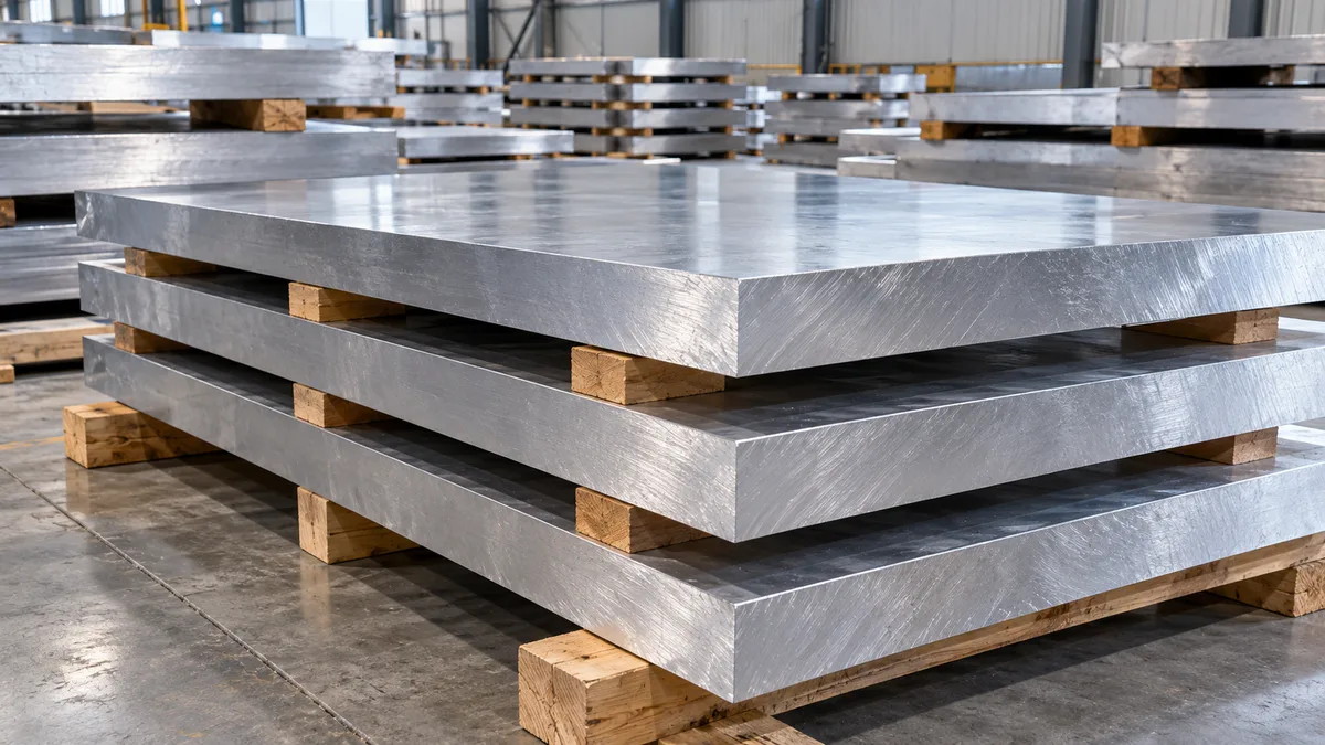
Most aluminium busbar is extruded or rolled to standard flat-bar sizes: roughly 2 – 40 mm thick and up to about 200 – 300 mm wide. Above that envelope, the press force and container size needed for a solid, high-purity section climb steeply, and a die for a one-off size is rarely economic. Sawing the bar from a thick rolled or hot-rolled plate removes those limits.
A heavy DC installation such as an aluminium potline, a chlor-alkali cell room or a large rectifier station may need a single conductor of 50,000 – 70,000 mm2 or more. Making that from several thinner bars bolted in parallel adds joints, each of which adds contact resistance, heat and a maintenance point. A monolithic bar cut from 100 – 120 mm plate carries the same current with fewer interfaces.
Plate is also the practical answer when the conductor is not a simple straight bar: L-shaped lugs, wide terminal pads, stepped thickness transitions and flag connectors can be profiled directly from the plate by sawing, CNC milling or waterjet cutting, and then joined to straight runs by welding.
| Criterion | Standard extruded / rolled busbar | Plate-cut large busbar |
|---|---|---|
| Typical size range | About 2 – 40 mm thick, 10 – 300 mm wide, 3 – 6 m lengths | Commonly 20 – 120 mm thick (heavier on request), up to ~600 mm wide, lengths to the 10 m class |
| How it is made | Extruded through a die or rolled and slit to a catalogue size | Sawn or milled from thick plate to the customer drawing |
| Edges | Rounded or radiused edges from the die | Square sawn edges; radiusing or chamfering is a machining option |
| Secondary work | Cut to length, punch or drill, bend, insulate | Hole and slot machining, end milling, bending of thinner sections, welded flexible connections |
| Critical inspection points | Section size, length, hole pitch, surface | Flatness, camber, cut squareness, burrs and protection against transport damage |
| Where it is used | Switchgear, busway, panel and distribution connections | Rectifiers, electrolysis and smelting, generator and transformer leads, furnace supply |
Extruded busbar is still the right answer up to its size limit: it has rounded edges that help with partial discharge in AC systems, tighter section tolerances and lower cost per kilogram. See our electrical busbar guide for standard sizes, and the tubular bus pipe guide where high AC currents favour a hollow conductor.
Conductivity falls as alloy content rises, so heavy DC conductors are almost always made from commercially pure 1xxx aluminium. A heat-treatable 6xxx grade is chosen when the bar must also carry mechanical load, hold bolt preload over decades or resist short-circuit forces without bending.
| Alloy | Al content | Typical conductivity | Strength | Best suited to |
|---|---|---|---|---|
| 1070 / 1070A | ≥ 99.70 % | About 61 – 62 % IACS | Low | Primary DC conductors, rectifier and electrolysis connections where conductivity is the priority |
| 1060 | ≥ 99.60 % | About 61 – 62 % IACS | Low | General conductive bars, cut parts and simple bent pieces; wide availability |
| 1350 (EC grade) | ≥ 99.50 %, with B, V, Ti, Cr controlled | 61.0 % IACS minimum (annealed higher) | Low | Conductor applications that must meet electrical-conductor specifications |
| 6101 | Al-Mg-Si | 55 – 59.5 % IACS depending on temper (T6 to T64) | Medium to high | Bolted joint areas, self-supporting runs, bars exposed to short-circuit forces |
Conductivity of 1xxx plate depends on purity and temper; 6101 values are the temper minimums in ASTM B317. Specify the required minimum % IACS on the order and it will be verified on the certificate.
For heavy bars the usual temper is H112 (as hot-rolled) or O (annealed). H112 plate keeps a modest work-hardened strength and machines more cleanly; annealed plate gives the highest conductivity and bends most easily but is soft enough to dent in handling. Cold-worked H14 or H18 tempers are rarely practical at these thicknesses.
If the design is close to its thermal limit, a 1 % IACS difference matters: over a 10 m run at 60,000 A it changes the I2R loss by tens of watts per metre. If the bar must also act as a structural member, 6101-T6 or T61 gives several times the yield strength of 1070 for a loss of only a few percent in conductivity.
Weight is cross-section × length × 2.70 g/cm3. DC resistance at 20 °C is shown for 61 % IACS material (resistivity 0.02826 Ω·mm2/m); at a typical operating temperature of 70 – 90 °C it is roughly 20 – 28 % higher. The table is a calculation aid, not a list of fixed sizes: plate-cut bars are made to the dimensions on your drawing.
| Section (mm) | Area (mm²) | kg per metre | kg per 10 m bar | DC resistance (µΩ/m, 20 °C) |
|---|---|---|---|---|
| 600 × 120 | 72,000 | 194.4 | 1,944 | 0.39 |
| 600 × 100 | 60,000 | 162.0 | 1,620 | 0.47 |
| 500 × 80 | 40,000 | 108.0 | 1,080 | 0.71 |
| 400 × 60 | 24,000 | 64.8 | 648 | 1.18 |
| 300 × 50 | 15,000 | 40.5 | 405 | 1.88 |
| 250 × 40 | 10,000 | 27.0 | 270 | 2.83 |
| 200 × 30 | 6,000 | 16.2 | 162 | 4.71 |
Sizing for current. Large DC conductors are not sized from a simple amps-per-mm2 rule. The designer balances temperature rise, power loss over the plant life, voltage drop, magnetic field effects (critical in electrolysis cells) and short-circuit forces. Published design figures for heavy DC bus are often well under 1 A/mm2, which is why such large sections are needed. Always confirm the section with a thermal calculation for the actual installation, ventilation and ambient temperature.
Long, heavy, soft bars move during cutting and handling, so shape tolerances deserve as much attention as nominal size. The values below are typical starting points for agreement; tighter figures are possible with machined faces and should be written on the drawing.
| Parameter | Typical range | Typical tolerance |
|---|---|---|
| Thickness | 20 – 180 mm | ± 1.0 to ± 3.0 mm (rolled faces), tighter if milled |
| Width | Up to ~600 mm | ± 2.5 to ± 3.0 mm sawn |
| Length | To ~15 m by agreement | − 0 / + 3 mm up to − 0 / + 20 mm on very long bars |
| Cut squareness (through thickness) | — | − 0 / + 1.0 to − 0 / + 3.0 mm |
| Flatness across width | — | ± 1.0 to ± 2.0 mm |
| Flatness / bow along length | — | − 0 / + 3 mm to − 0 / + 15 mm depending on length |
| Camber, waviness, end lift | — | As stated on the drawing |
Starting from stress-relieved or flattened plate reduces the bow that appears when a narrow strip is released from a wide plate. For long bars the cut direction is kept parallel to the rolling direction.
Saw-cut faces are deburred and all aluminium chips removed so they cannot be trapped in joints. Contact faces can be fly-cut or milled for flatness and low contact resistance.
Soft 1xxx bars bend under their own weight if lifted at one point. Lift with spreader beams or multiple slings and support on timber at close intervals.
Bolt holes, slotted holes for thermal movement and tapped holes are CNC machined to the drawing. Hole position tolerances refer to a datum edge, so specify which edge.
Ends can be milled square, stepped or reduced in thickness to mate with equipment terminals. Contact pads are machined flat to the finish your joint design requires.
Sections up to moderate thickness can be bent in annealed or H112 1xxx material; very thick bars are normally profiled from plate or welded at the corner instead of bent.
MIG or TIG welding with 1100 or 1188 filler joins straight runs to lugs and transitions while keeping conductivity close to the parent metal. 4043 filler is stronger but less conductive.
Laminated packs of thin aluminium sheet or foil, pressure- or fusion-welded at the ends, absorb thermal expansion, vibration and assembly misalignment. See flexible aluminium busbar.
Where a bar meets a copper terminal, an aluminium-copper transition plate or clad section avoids galvanic corrosion at the joint. See copper-clad aluminium busbar.
Aluminium forms a thin, hard oxide film within seconds of being cut. The film is harmless on the body of the bar but raises resistance in bolted joints, so joint preparation and plating decisions are made zone by zone.
| Treatment | Purpose | Notes |
|---|---|---|
| Cleaning and deburring | Removes chips, burrs and oil | Standard on every bar |
| Wire brushing + contact compound | Breaks oxide and seals the joint | Done at installation on bare aluminium joints |
| Tin plating | Stable, low-resistance contact surface | Most common plating for aluminium bus joints; see tin plated aluminium busbar |
| Nickel plating | Corrosion and wear resistance at contact zones | Used in aggressive or high-temperature atmospheres |
| Silver plating | Lowest contact resistance | For high-reliability, high-current contacts; specified area only |
| Insulating coating or sleeving | Phase isolation, touch protection, identification | Masked away from contact faces |
In electrolysis plants the bar is often left bare because the atmosphere attacks most coatings and the joints are welded rather than bolted. In switchgear and generator connections, plated contact pads with masked insulation elsewhere are normal. State on the drawing which faces are contact faces so that masking and machining are done in the right places.
A typical example: an electrolysis plant needs ten straight conductors of 600 × 120 mm, 10 m long, in 1070A-H112, with machined contact pads at each end and slotted bolt holes for thermal movement. Each bar weighs close to two tonnes, so the order also covers lifting points, timber supports and a long-load transport plan.
Rarely. Solid high-purity sections of that size need very large presses and a dedicated die, which is uneconomic for most projects. Sawing the bar from thick plate is the usual route for sections above roughly 300 mm wide or 40 mm thick.
1070A and 1060 give about 61 – 62 % IACS and are the normal choice for heavy DC conductors. 1350 is used where an electrical-conductor specification applies. Choose 6101 when the bar also needs strength, accepting 55 – 59.5 % IACS depending on temper.
The cross-section is 72,000 mm², so it weighs about 194 kg per metre, or roughly 1.94 tonnes for a 10 m bar.
Specify thickness, width and length tolerances, plus flatness across the width, bow along the length, camber and cut squareness. Typical starting values are ± 1 – 3 mm on thickness, ± 2.5 – 3 mm on width and − 0 / + 3 to + 20 mm on length; machined contact faces can be held much tighter.
Plate only the contact zones when joints are bolted and the atmosphere allows it; tin is the usual choice. Welded joints and bars in electrolysis cell rooms are usually left bare.
Yes. Metline supplies the bars cut to drawing with holes, slots, end machining and contact-face finishing on request, with EN 10204 3.1 certificates and export packing for long loads.
Send the drawing, alloy, temper and quantity. We will confirm the plate route, tolerances, processing and delivered price.





