Drawn seamless tube
Extruded hollow is cold-drawn over a mandrel through a die to final size. This gives tight OD and wall tolerances, a smooth bore and a bright finish. Required for hydraulic and fuel lines (AMS 4081, 4083).



6061 aircraft tube is drawn seamless or extruded 6061 tubing made and certified to aerospace specifications such as AMS 4079, AMS 4080, AMS 4081, AMS 4082 and AMS 4083. It is the standard aluminium tube for aircraft hydraulic and fuel lines, conduits, structural struts and airframe tubing that must bend, flare and weld well. Metline supplies 6061 tube in O, T4 and T6 tempers, round, square and rectangular, to customers worldwide.
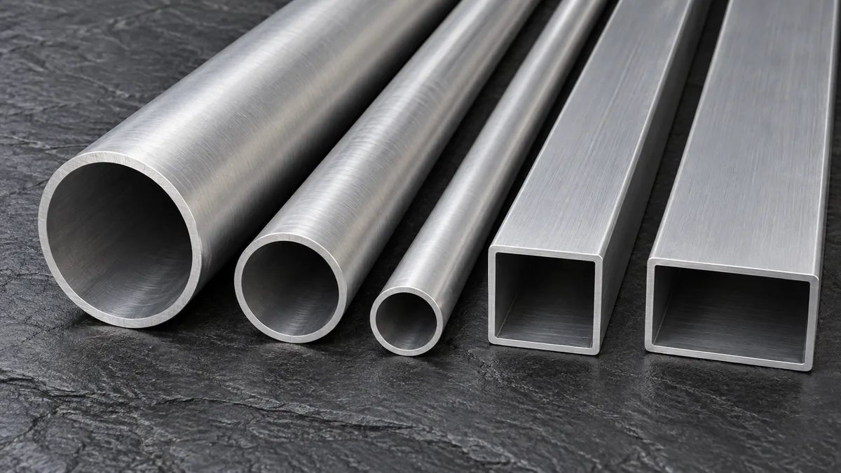
Not every 6061 tube qualifies for aircraft use. "Aircraft" or "aerospace" tube is 6061 that is drawn or extruded, heat-treated, tested and certified to an aerospace material specification, with traceability from the cast to the finished length. The alloy is standard 6061; the specification, the tighter tolerances and the extra tests are what make it flight material.
6061 became the default aluminium tube in aircraft because it combines three things that hydraulic and structural tubing needs: it bends and flares without cracking in T4 or T6, it resists corrosion well without cladding, and it welds with common TIG and MIG procedures. Seamless drawn 6061-T6 tube is used for medium-pressure hydraulic return and pressure lines, fuel and oil lines, and pneumatic systems. Thicker-walled drawn and extruded tube becomes control rods, struts, frames and seat and cargo structures.
Higher-pressure hydraulic lines on large aircraft often use titanium or stainless steel, and 2024-T3 tube is chosen where higher strength is needed. 6061 remains the tube of choice where pressure and temperature allow it, because it is easier to form and install and costs less.
The specification on the drawing sets the manufacturing route, temper and tests. These are the documents most often called up for 6061 tubing:
| Specification | Product | Temper | Typical use |
|---|---|---|---|
| SAE AMS 4079 | Drawn seamless round tube, close tolerance | O | Lines to be formed and heat-treated by the user |
| SAE AMS 4080 | Drawn seamless tube | O | Conduits and low-pressure fluid lines; wall 0.46 – 12.70 mm |
| SAE AMS 4081 | Drawn seamless hydraulic tube | T4 | Hydraulic lines needing maximum formability for flaring |
| SAE AMS 4082 | Drawn seamless tube | T6 | Brackets, conduits, low-pressure lines; wall 0.64 – 12.70 mm |
| SAE AMS 4083 | Drawn seamless hydraulic tube | T6 | Hydraulic pressure and return lines; wall 0.64 – 12.70 mm |
| SAE AMS 4150 | Extruded bar, rod, profiles and tube | T6 | Structural tube and extruded shapes |
| SAE AMS 4173 | Extruded tube and profiles, stress-relieved | T6510 / T6511 | Machined tubular parts needing straightness and stability |
| AMS-T-7081 | Seamless drawn hydraulic tube (former MIL-T-7081) | T4, T6 | Legacy drawings for hydraulic lines |
| ASTM B210 / B210M | Drawn seamless tube, general | O, T4, T6 | Commercial and industrial equivalent of drawn tube |
| ASTM B221 / B241 / B429 | Extruded tube; seamless pipe; structural pipe and tube | T4, T6, T6511 | Commercial extruded tube and pipe |
Former federal specifications such as WW-T-700/6 (6061 drawn tube) have been replaced by AMS or ASTM documents. If an old drawing calls for them, tell us and we will propose the current equivalent for your approval.
All 6061 tube specifications use the registered Aluminum Association composition. The mill certificate reports the actual analysis of each cast.
| Element | Minimum | Maximum | Role in the alloy |
|---|---|---|---|
| Silicon (Si) | 0.40 | 0.80 | Forms the strengthening Mg2Si phase with magnesium |
| Iron (Fe) | — | 0.70 | Impurity; held low for toughness and surface quality |
| Copper (Cu) | 0.15 | 0.40 | Adds strength; a small penalty in corrosion resistance |
| Manganese (Mn) | — | 0.15 | Grain structure control |
| Magnesium (Mg) | 0.80 | 1.20 | Main strengthening element with silicon |
| Chromium (Cr) | 0.04 | 0.35 | Limits recrystallisation, improves stress-corrosion resistance |
| Zinc (Zn) | — | 0.25 | Impurity |
| Titanium (Ti) | — | 0.15 | Grain refiner |
| Others, each / total | — | 0.05 / 0.15 | |
| Aluminium (Al) | Remainder | About 95.8 – 98.6 % |
Drawn tube reaches slightly higher guaranteed strength than extruded tube in the same temper, because cold drawing refines the structure and the ASTM and AMS tables for drawn tube set higher minimums. The values below are minimums (or maximums for O temper) from ASTM B210 and B221 and the matching AMS documents; typical values are given for comparison.
| Product and temper | Tensile strength | Yield strength (0.2 %) | Elongation (min, in 2 in / 50 mm) |
|---|---|---|---|
| Drawn tube, O (max) | ≤ 150 MPa / 22 ksi | ≤ 97 MPa / 14 ksi | 15 – 20 % (wall dependent) |
| Drawn tube, T4 (min) | 205 MPa / 30 ksi | 110 MPa / 16 ksi | 14 – 16 % |
| Drawn tube, T6 (min) | 290 MPa / 42 ksi | 240 MPa / 35 ksi | 8 – 10 % |
| Extruded tube, T4 (min) | 180 MPa / 26 ksi | 110 MPa / 16 ksi | 16 % |
| Extruded tube, T6 / T6511 (min) | 260 MPa / 38 ksi | 240 MPa / 35 ksi | 8 – 10 % |
| 6061-T6, typical | 310 MPa / 45 ksi | 276 MPa / 40 ksi | 12 – 17 % |
Exact elongation limits depend on wall thickness and whether a full-section or strip specimen is tested. Your certificate states the actual results against the ordered specification.
For hydraulic design, allowable working pressure depends on outside diameter, wall thickness, temperature and the safety factor in the system standard, not just tensile strength. Burst pressure is often estimated with Barlow's formula (P = 2·S·t / D), but the governing aircraft or system specification sets the factor between burst and working pressure.
Extruded hollow is cold-drawn over a mandrel through a die to final size. This gives tight OD and wall tolerances, a smooth bore and a bright finish. Required for hydraulic and fuel lines (AMS 4081, 4083).
Pushed through a die over a mandrel from a pierced or hollow billet, with no weld seam. Larger sizes and thicker walls than drawn tube; used for structural parts and machined sleeves.
Extruded through a bridge or porthole die, so the metal flows round the mandrel and rejoins in solid-state weld lines. Fine for frames and railings, but not accepted where a specification requires seamless tube for pressure service.
Seamless drawn tube in T4 or T6, with extra tests such as flaring, flattening and eddy-current or pressure testing, plus strict limits on surface and bore defects.
Extruded or drawn 6061-T6 pipe to ASTM B241 or B429 in ASME pipe sizes. Common on ground equipment, test rigs and tooling.
Extruded or drawn shapes in T6 for frames, seat structure, wing ribs in light aircraft and drone booms. Oval and streamline tube suits struts and fairings.
Hydraulic tube is normally ordered in imperial sizes (for example 3/8 in × 0.035 in) to match AN, MS and AS fittings.
Common aircraft hydraulic and fluid-line sizes, with weight per metre of 6061 (density 2.70 g/cm³):
| OD (in) | Wall (in) | OD × wall (mm) | kg per metre | lb per foot |
|---|---|---|---|---|
| 1/4 | 0.035 | 6.35 × 0.89 | 0.041 | 0.028 |
| 5/16 | 0.035 | 7.94 × 0.89 | 0.053 | 0.036 |
| 3/8 | 0.035 | 9.52 × 0.89 | 0.065 | 0.044 |
| 3/8 | 0.049 | 9.52 × 1.24 | 0.087 | 0.059 |
| 1/2 | 0.035 | 12.70 × 0.89 | 0.089 | 0.060 |
| 1/2 | 0.049 | 12.70 × 1.24 | 0.121 | 0.081 |
| 5/8 | 0.035 | 15.88 × 0.89 | 0.113 | 0.076 |
| 5/8 | 0.049 | 15.88 × 1.24 | 0.154 | 0.104 |
| 3/4 | 0.049 | 19.05 × 1.24 | 0.188 | 0.126 |
| 3/4 | 0.065 | 19.05 × 1.65 | 0.244 | 0.164 |
| 1 | 0.049 | 25.40 × 1.24 | 0.255 | 0.171 |
| 1 | 0.065 | 25.40 × 1.65 | 0.333 | 0.223 |
| 1-1/4 | 0.065 | 31.75 × 1.65 | 0.422 | 0.283 |
| 1-1/2 | 0.065 | 38.10 × 1.65 | 0.510 | 0.343 |
| 2 | 0.083 | 50.80 × 2.11 | 0.871 | 0.585 |
6061-T6 pipe in standard ASME B36.10 dimensions:
| NPS | OD (in / mm) | Sch 40 wall (in) | Sch 40 kg/m | Sch 80 wall (in) | Sch 80 kg/m |
|---|---|---|---|---|---|
| 1/2 | 0.840 / 21.3 | 0.109 | 0.44 | 0.147 | 0.56 |
| 3/4 | 1.050 / 26.7 | 0.113 | 0.58 | 0.154 | 0.76 |
| 1 | 1.315 / 33.4 | 0.133 | 0.86 | 0.179 | 1.11 |
| 1-1/4 | 1.660 / 42.2 | 0.140 | 1.16 | 0.191 | 1.54 |
| 1-1/2 | 1.900 / 48.3 | 0.145 | 1.39 | 0.200 | 1.86 |
| 2 | 2.375 / 60.3 | 0.154 | 1.87 | 0.218 | 2.57 |
| 2-1/2 | 2.875 / 73.0 | 0.203 | 2.97 | 0.276 | 3.93 |
| 3 | 3.500 / 88.9 | 0.216 | 3.88 | 0.300 | 5.25 |
| 4 | 4.500 / 114.3 | 0.237 | 5.53 | 0.337 | 7.68 |
| 6 | 6.625 / 168.3 | 0.280 | 9.72 | 0.432 | 14.64 |
| 8 | 8.625 / 219.1 | 0.322 | 14.63 | 0.500 | 22.23 |
| 10 | 10.750 / 273.1 | 0.365 | 20.74 | 0.594 | 33.01 |
| 12 | 12.750 / 323.8 | 0.406 | 27.43 | 0.687 | 45.35 |
Wall thicknesses follow ASME B36.10; weights are calculated for 6061 at 2.70 g/cm³. Use the tube weight calculator for other sizes.
Drawn tube to AMS specifications is held to the close-tolerance tables for OD, wall and straightness in ANSI H35.2, with some specifications (such as AMS 4079) calling for tighter "close tolerance" limits. Extruded tube follows the extruded-product tables, which are wider.
Lengths are capped or plugged at both ends and packed in rigid cases, so the bore stays clean. Hydraulic tube is often required to be supplied clean and dry inside, free from chips and drawing lubricant residue; state any cleanliness requirement on the order.
Use mandrel benders for thin walls. T4 bends more tightly than T6; a centreline radius of about 3 × OD is a common starting point for T6 hydraulic tube, with tighter radii possible in T4 or O.
37° flares for AN/MS fittings are routinely made in T4 and T6 drawn tube. Use correctly sized flaring tools and deburr the tube end to avoid split flares.
Beads for hose clamps and swaged permanent fittings are common in fuel and air lines; follow the fitting maker's tooling data.
TIG and MIG with 4043 or 5356 filler. Strength near the weld falls towards T4 levels unless the assembly is solution treated and aged again.
O and T4 tube can be formed and then aged to T6. Aerospace heat treatment follows AMS 2770 with pyrometry to AMS 2750.
Anodise (Type II or III) or apply conversion coating for corrosion protection and primer adhesion; colour anodising is used to identify systems.
| System or part | Typical tube form | Usual temper |
|---|---|---|
| Hydraulic pressure and return lines | Drawn seamless hydraulic tube (AMS 4083 / 4081) | T6 or T4 |
| Fuel, oil and coolant lines | Drawn seamless tube | T6 or O |
| Pneumatic, vent and drain lines | Drawn seamless tube | T6 or O |
| Electrical conduit | Drawn tube (AMS 4080 / 4082) | O or T6 |
| Control rods and push-pull tubes | Drawn or extruded round tube | T6 |
| Struts, frames and seat structure | Extruded round, square and rectangular tube | T6 |
| Ground-support equipment and stands | Extruded tube and Schedule 40/80 pipe | T6 |
| Satellite and launch-vehicle trusses and lines | Drawn or extruded tube | T6 |
| Drone booms and light-aircraft fuselage frames | Drawn or extruded round and square tube | T6 |
A typical light-aircraft or business-jet hydraulic installation illustrates the choices. Pressure lines in the wheel wells, where tubes are short and heavily bent, are made from T4 tube to AMS 4081 so that tight bends and 37° flares form without cracking. Long straight runs through the fuselage use T6 tube to AMS 4083 for the extra strength margin. Low-pressure return and case-drain lines may use thinner walls in the same alloy, and conduits for wiring use O or T6 general-purpose tube to AMS 4080 or AMS 4082. Every length is identified by specification and lot, so a replacement line made years later can be traced back to the same requirements.
The same tube is used widely outside aerospace: bicycle and motorcycle frames, sports equipment, truck and trailer frames, marine railings and towers, scaffolding and structural framing, and tubular bus conductors in substations.
| Property | 6061-T6 | 2024-T3 | 5052-O / H32 | 3003-H14 | 6063-T6 |
|---|---|---|---|---|---|
| Typical tensile strength | 310 MPa | 485 MPa | 195 – 230 MPa | 150 MPa | 240 MPa |
| Formability (flaring, bending) | Good (better in T4) | Fair | Very good | Excellent | Good |
| Weldability | Good | Poor | Excellent | Excellent | Good |
| Corrosion resistance | Very good | Fair | Excellent | Excellent | Very good |
| Typical aircraft use | Hydraulic, fuel lines, structure | High-strength lines and struts | Fuel and oil lines | Low-pressure lines, ducts | Trim, non-structural frames |
Choose 2024-T3 where higher tube strength is needed and welding is not, 5052 for very formable fuel and oil lines, 3003 for low-pressure ducting, and 6063 for decorative or lightly loaded frames. 6061 covers the middle ground and is the most widely available aircraft tube alloy.
AMS 4083 covers seamless drawn 6061-T6 hydraulic tube. AMS 4081 covers the same product in T4 for easier flaring and bending; older drawings may cite AMS-T-7081 (formerly MIL-T-7081).
Both are drawn seamless 6061-T6 tube. AMS 4083 is the hydraulic grade with extra formability and inspection requirements for pressure lines; AMS 4082 is general-purpose tube for brackets, conduits and low-pressure lines.
No. Porthole tube contains extrusion weld lines. Pressure and fluid lines need seamless drawn tube to an aerospace hydraulic specification.
T6 for straight runs and moderate bends where full strength is wanted. T4 where tight bends or heavy flaring are needed; T4 tube can be aged to T6 after forming if the strength is required.
Weight per metre = π × (OD − wall) × wall × 2.70 / 1000, with dimensions in mm. A 3/8 in × 0.035 in tube weighs about 0.065 kg/m; 2 in Schedule 40 pipe about 1.87 kg/m.
Yes. Drawn seamless 6061 in O or T6 is widely used for fuel, oil and vent lines, as is 5052. The system specification sets the alloy, temper and pressure rating.
Yes. Tube is supplied in random, fixed or cut lengths, capped and packed in rigid cases, with an EN 10204 3.1 certificate to the ordered specification, to customers worldwide.
Send the size, temper, length, quantity and specification. Our team will reply with availability, test plan and a delivered price.





