


Inner Grooved Aluminium Tube: How Groove Geometry Drives Performance
An inner grooved (micro-fin) tube has dozens of fine spiral or straight ribs on its bore that increase the wetted area and disturb the refrigerant film, so a coil of the same size transfers noticeably more heat than one built with smooth tube. This guide explains the geometry parameters on a grooved-tube drawing, how they trade heat transfer against pressure drop, and what to check when switching a coil design to aluminium.
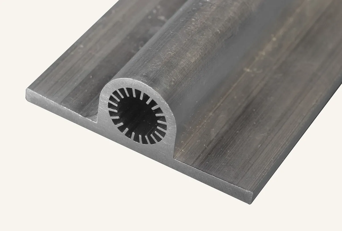
- Alloys
- 1060, 3003, 3103
- Outer diameter
- About 5 – 16 mm
- Groove depth
- 0.05 – 0.35 mm
- Supply
- Level-wound coil or straight lengths
What an inner grooved tube is and why it works
Micro-fin tubes were introduced for air-conditioner coils in Japan in the late 1970s and quickly became the standard tube for fin-and-tube heat exchangers. They were first made in copper; the same principle is now applied to aluminium tube as manufacturers move to all-aluminium coils.
Inside a coil the refrigerant boils (evaporator) or condenses (condenser) as a two-phase flow. In a smooth tube the liquid tends to collect at the bottom and the upper wall runs comparatively dry during evaporation, while during condensation a liquid film builds up and insulates the wall. Fine grooves change both behaviours: capillary action pulls liquid up around the circumference so more of the wall stays wet, the ribs break up the condensate film, and the extra surface adds area.
Published studies of micro-fin tubes commonly report in-tube heat-transfer coefficients well above those of smooth tubes at the same mass flux, with a smaller relative increase in pressure drop. The exact gain depends on refrigerant, mass flux and groove design, which is why groove geometry is specified so carefully. The result is either more capacity from the same coil, or the same capacity from a smaller coil with less refrigerant charge.
The geometry on an inner grooved tube drawing
| Parameter | Symbol | Typical range | Effect |
|---|---|---|---|
| Outer diameter | D | 5 – 16 mm | Sets coil circuitry, fin collar size and refrigerant velocity |
| Bottom (root) wall thickness | tb | 0.20 – 0.50 mm | Governs burst pressure and resistance to collapse during expansion |
| Groove (fin) height | h | 0.05 – 0.35 mm | Taller fins add area and liquid-film disruption, but raise pressure drop and weight |
| Number of grooves | n | About 30 – 100 | More grooves add area; too many narrow the channels and flood with liquid |
| Helix (lead) angle | β | 0° (straight) to about 30° | A spiral swirls the liquid around the bore; higher angles raise both heat transfer and pressure drop |
| Apex (tooth top) angle | γ | About 10° – 60° | Sharper teeth give more area per gram but deform more during expansion |
These parameters interact. A designer might increase groove count and reduce fin height to keep pressure drop in check, or choose a moderate helix angle (often around 15 – 25°) as a balance between heat transfer and pumping loss. Because each refrigerant and coil duty favours a different combination, groove profiles are usually developed with the coil maker and qualified on a test rig.
Typical geometry windows by outer diameter
The table shows the geometry windows commonly used for each tube size. It is a design starting point, not a catalogue: the final profile is defined on the customer's drawing.
| OD (mm) | Root wall tb (mm) | Groove depth h (mm) | Apex angle γ (°) | Helix angle β (°) | Grooves n |
|---|---|---|---|---|---|
| 5.00 | 0.20 – 0.23 | 0.12 – 0.15 | 11 – 40 | 18 – 40 | 40 – 58 |
| 6.35 | 0.23 – 0.27 | 0.15 – 0.16 | 12 – 40 | 18 – 28 | 45 – 54 |
| 7.00 | 0.21 – 0.27 | 0.10 – 0.24 | 10 – 53 | 15 – 40 | 50 – 70 |
| 7.94 – 8.00 | 0.23 – 0.41 | 0.12 – 0.22 | 12 – 42 | 18 – 43 | 50 – 80 |
| 9.52 | 0.27 – 0.45 | 0.15 – 0.25 | 20 – 90 | 15 – 30 | 55 – 85 |
| 11.90 – 12.00 | 0.32 – 0.40 | 0.17 – 0.25 | 15 – 55 | 16 – 30 | 70 – 98 |
| 12.70 | 0.32 – 0.41 | 0.23 – 0.25 | 30 – 58 | 18 – 30 | 70 – 75 |
| 15.00 – 15.90 | 0.35 – 0.50 | 0.25 – 0.35 | 30 – 53 | 18 – 30 | 30 – 75 |
Aluminium tube for high-pressure refrigerants such as R410A and R32 generally needs a heavier root wall than the equivalent copper tube; confirm burst and fatigue margins for your operating pressures.
Aluminium alloys for grooved tube
| Alloy | Character | When to use it |
|---|---|---|
| 1060 / 1050 | Commercially pure; highest conductivity and drawability | Fine grooves and thin walls at moderate pressure; easiest to form |
| 3003 / 3103 | Al-Mn; higher strength with good corrosion resistance | Higher-pressure refrigerants and thinner root walls; the most common choice |
| Modified 3xxx long-life alloys | Controlled Cu, Zn and Mn for corrosion behaviour | Coils exposed to coastal or polluted air, often paired with sacrificial fins |
3003 is stronger than 1060 but harder to draw, so very fine, tall grooves are easier to form in purer alloys. Tubes are usually supplied in the O temper for bending into hairpins, or lightly hardened when straight lengths must stay rigid. Corrosion protection is designed as a system: fins are normally anodic to the tube so that they corrode sacrificially, and a zinc diffusion layer on the tube surface can provide a further sacrificial barrier.
Aluminium vs copper inner grooved tube
| Factor | Aluminium (1060 / 3003) | Copper (phosphorus-deoxidised) |
|---|---|---|
| Density | 2.70 – 2.73 g/cm³ | About 8.9 g/cm³ (roughly three times heavier) |
| Thermal conductivity | About 190 – 230 W/m·K depending on alloy | About 340 – 390 W/m·K |
| Wall needed for pressure | Thicker, because strength is lower | Thinner |
| Coil with aluminium fins | Single-metal coil, no galvanic couple between tube and fin | Bimetallic coil; corrosion at the tube-fin interface in aggressive air |
| Joining | Brazing with Al-Si filler and flux, or Zn-Al filler for Al-Cu joints | Brazing with copper-phosphorus fillers |
| Material price behaviour | Lower and historically less volatile per metre of tube | Higher and more volatile |
| Recycling | All-aluminium coil recycles without separating metals | Tube and fins must be separated for best scrap value |
Copper's higher conductivity matters less than it seems, because in a fin-and-tube coil most of the thermal resistance is on the air side, not in the tube wall. The real engineering changes when moving to aluminium are wall thickness for pressure, the brazing process for return bends and connections, and corrosion design. Joints between aluminium coils and copper line sets need a proper transition joint so that galvanic corrosion does not occur.
Expansion, bending and brazing points
- Mechanical expansion: tubes are expanded into the fin collars with a bullet or hydraulic expander. The expander also presses on the groove tips; too much expansion flattens them and lowers performance, too little leaves poor fin contact. Bullet size and expansion ratio should be qualified for aluminium tube.
- Hairpin bending: soft O-temper tube bends into tight hairpins; check for wall thinning and ovality on the outside of the bend.
- Return bends and headers: brazed with Al-Si filler rings and flux, or by controlled-atmosphere brazing. Keep the joint clean and free of stamping oil.
- Cleanliness: internal cleanliness and dryness matter for refrigerant systems; tubes are cleaned, dried and sealed with end caps.
- Leak and pressure test: coils are pressure-tested and leak-checked after brazing; tube supply should come with eddy-current testing where specified.
What to send when ordering inner grooved tube
- GeometryOD, root wall, groove depth, groove count, helix and apex angles, or a sample or drawing.
- MaterialAlloy and temper (e.g. 3003-O), and the governing standard such as ASTM B210 or EN 754 with agreed tolerances.
- Supply formLevel-wound coil (with coil weight and ID/OD) or straight lengths; end caps and internal cleanliness requirements.
- TestingEddy-current testing, burst test, groove profile checks and any corrosion test such as SWAAT or salt spray.
- Documents and shippingMill test certificate to EN 10204 3.1, export packing, and delivery terms (EXW, FOB, CIF or DAP).
References and standards
- ASTM B210 – Standard Specification for Aluminum and Aluminum-Alloy Drawn Seamless Tubes
- ASTM B483 – Standard Specification for Aluminum and Aluminum-Alloy Drawn Tube and Pipe for General Purpose Applications
- EN 754-7 – Aluminium and aluminium alloys: cold drawn rod/bar and tube, seamless tubes, tolerances
- ASHRAE Handbook – Fundamentals, chapter on two-phase heat transfer and pressure drop
- The Aluminum Association – International Alloy Designations and Chemical Composition Limits
Inner grooved aluminium (aluminum) tube: FAQ
Can aluminium inner grooved tube match copper performance?
In fin-and-tube coils the air side dominates thermal resistance, so a well-designed aluminium grooved tube coil can reach performance close to an equivalent copper coil. The design usually needs a heavier root wall and a qualified expansion process.
Is a deeper groove or more grooves always better?
No. Taller fins and more grooves add area, but they raise pressure drop and weight and can flood with liquid at low mass flux. The best geometry depends on refrigerant, tube size and duty.
What is the difference between straight and spiral grooves?
Straight grooves run along the tube axis and add area with low pressure drop. Spiral (helical) grooves also swirl the liquid around the bore, which usually gives more heat transfer at the cost of higher pressure drop.
Which alloy is used for aluminium grooved tube?
3003 and 3103 are the most common, for their strength and corrosion resistance; 1060 and 1050 are used where fine grooves and maximum drawability matter.
Can you supply coiled tube for automatic hairpin benders?
Yes. Grooved tube can be supplied level-wound in coils for automatic straightening, cutting and hairpin bending, or in straight lengths.
How is corrosion prevented in all-aluminium coils?
By making the fins slightly anodic to the tube so that they protect it sacrificially, by using long-life tube alloys or a zinc diffusion layer, and by coated fins in aggressive environments.
Need inner grooved aluminium tube?
Send the groove drawing or sample, alloy, OD and wall, supply form and annual volume. We will reply with what we can supply and a delivered price.






