Straight-fin (plate-fin)
Parallel fins rising from a flat base. The default design for power supplies, motor drives and board-level cooling, and the most efficient when air flows along the fins.



An extruded aluminium heat sink is a finned profile pushed through a die in one piece, then cut to length, so the base and fins form a continuous path for heat to flow from a component into the surrounding air. Metline supplies heat sink extrusions in 6063, 6060, 6061 and 1xxx alloys, as cut lengths or as fully machined and anodised parts, for power electronics, LED lighting, telecoms and industrial equipment worldwide.
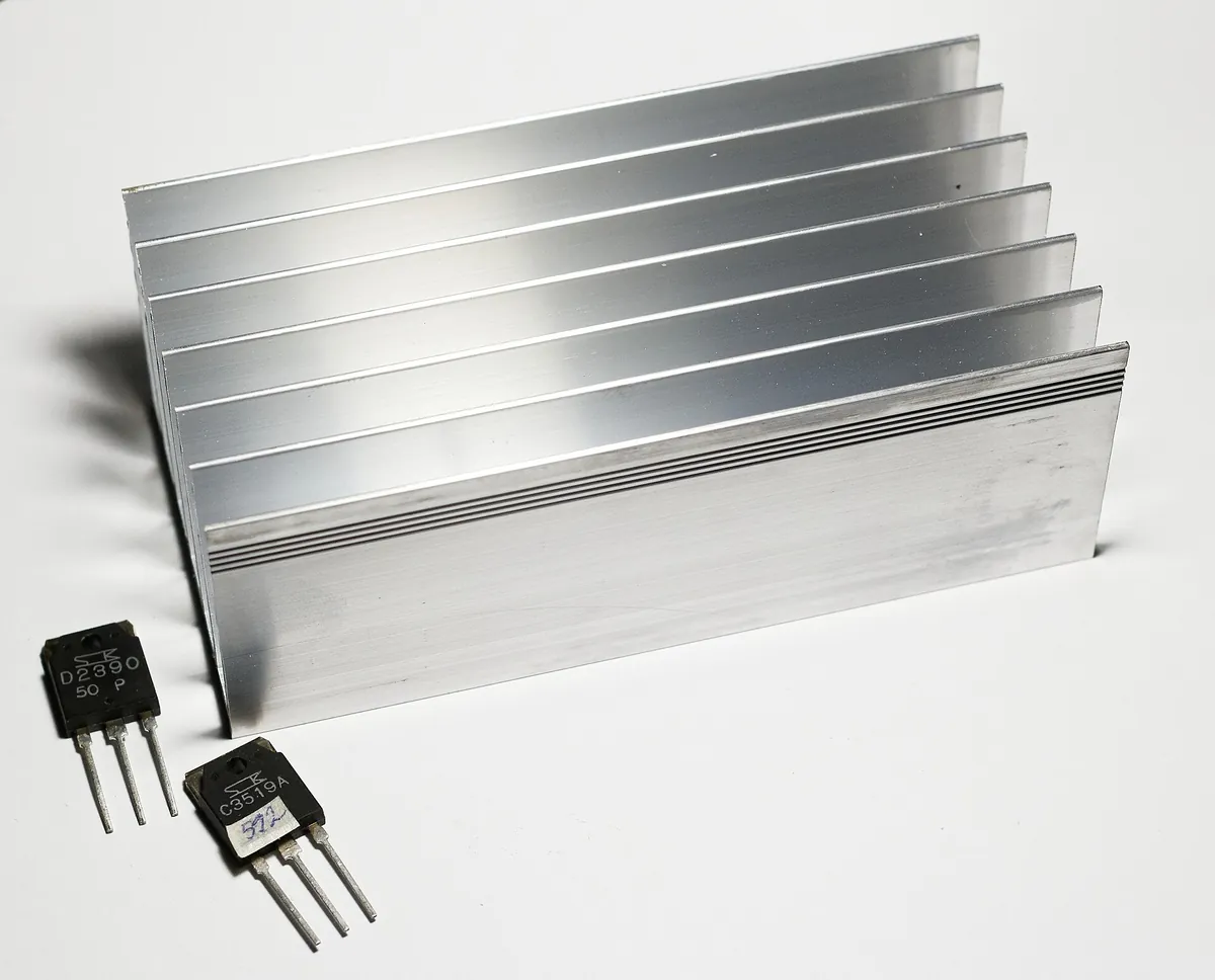
Every electronic device turns part of its power into heat. A heat sink spreads that heat out of a small, hot component and offers a large finned surface to the air, keeping the component below its maximum junction temperature. Extrusion is the most economical way to make that finned shape in volume.
Aluminium wins over copper for most heat sinks on balance rather than on conductivity alone. Copper conducts about twice as well (around 390 W/m·K against roughly 200 W/m·K for 6063), but it is more than three times as dense and considerably more expensive, and it cannot be extruded into thin, tall fins. For a given weight and cost, an aluminium extrusion usually removes more heat; copper is reserved for small, very high flux spots, often as an insert or base plate under an aluminium fin stack.
The extrusion process also suits thermal design. One die produces a profile of constant cross-section in long lengths, so a single tool can serve heat sinks of 30 mm or 300 mm simply by cutting to different lengths. Cooling performance can be tuned later by changing the cut length, adding a fan, or machining pockets and mounting holes without new tooling.
Parallel fins rising from a flat base. The default design for power supplies, motor drives and board-level cooling, and the most efficient when air flows along the fins.
Fins set at an angle to fit an enclosure, to direct airflow, or to give more fin length within a low height.
Fins radiating from a central core, used in downlights, spotlights and street lights. Works with air from any direction and suits natural convection when mounted vertically.
A straight-fin extrusion cross-cut by sawing or milling into an array of pins, so air can enter from any direction. Good in unpredictable airflow and in natural convection with horizontal mounting.
A profile that forms the housing of the electronics as well as the cooler, such as amplifier cases, inverter housings and LED drivers.
Wide-base sections for IGBT modules, welders and inverters, often combined with fans or bonded-fin extensions where fins must be very tall.
Thermal conductivity falls as alloying content rises, but so does extrudability for thin fins. 6063-T5 is the standard compromise: high conductivity, excellent extrudability, good anodising and enough strength for mounting.
| Alloy and temper | Thermal conductivity (typical) | Typical tensile strength | When to choose it |
|---|---|---|---|
| 6063-T5 | about 200 – 209 W/m·K | about 185 MPa | Default for most heat sinks; thin fins, fine pitch, even anodising |
| 6063-T6 | about 200 W/m·K | about 240 MPa | Where mounting loads or clips need a harder profile |
| 6060-T5 | about 200 – 210 W/m·K | about 185 – 190 MPa | European equivalent to 6063; very easy to extrude |
| 6061-T6 | about 167 W/m·K | about 310 MPa | Heat sinks that are also structural: chassis, housings, frames |
| 1050A / 1070 | about 222 – 230 W/m·K | about 75 – 110 MPa | Maximum conductivity where loads are very light; simpler sections |
Values are typical published figures for the temper; conductivity varies slightly with exact composition and heat treatment. Electrical conductivity of 6063-T5 is roughly 53 – 55 % IACS.
Heat sink selection starts with a thermal budget. The total allowed thermal resistance from the component junction to the air is the temperature rise you can accept divided by the power dissipated. The heat sink must take whatever is left after the component package and the thermal interface material have used their share.
| Design factor | Natural convection | Forced air (fan) |
|---|---|---|
| Fin spacing (gap) | Wider, roughly 6 – 12 mm, so warm air can rise freely | Narrower, roughly 2 – 5 mm, for more surface area |
| Fin orientation | Vertical fins, aligned with rising air | Aligned with the fan airflow |
| Surface finish | Anodising matters: raises emissivity from about 0.05 – 0.1 to around 0.8 | Radiation is minor; finish chosen for protection and appearance |
| Base thickness | Thicker bases spread heat from small sources across more fins | Same; also leaves material for tapped mounting holes |
Extrusion sets practical limits on fin geometry. The ratio of fin height to the gap between fins is the key one: conventional dies comfortably produce ratios of around 6:1 to 10:1, and specialised dies can go higher. Fins are normally 1 – 2 mm thick, with a slight taper towards the tip. Beyond these limits, bonded-fin, skived or brazed constructions are used instead.
Many common heat sink sections can be supplied from existing dies, avoiding tooling cost. For a new profile, send the envelope, power and airflow so the section can be reviewed for extrudability before the die is made.
| Example envelope (W × H) | Typical use |
|---|---|
| about 20 × 10 mm | TO-220 and small regulators |
| about 50 – 65 × 20 – 32 mm | DC/DC converters, small power supplies |
| about 100 – 125 × 20 – 60 mm | Motor drives, audio amplifiers, LED drivers |
| about 150 – 260 × 40 – 80 mm | IGBT modules, inverters, welding equipment |
| about 350 – 410 × 60 – 70 mm | High-power converters, rack-mounted equipment |
Saw cutting to length with deburred ends; tight length tolerances for automated assembly.
Mounting holes, tapped threads, pockets for components, fin removal for clearance, and flycutting of the base for flat contact.
Sawing or milling across the fins to make pin-fin heat sinks from a straight-fin profile.
Clear or black anodising to MIL-A-8625 Type II, typically 10 – 25 µm. Improves corrosion resistance and emissivity; the film is an electrical insulator, so mask contact areas if grounding is needed.
Trivalent (RoHS-compliant) chromate conversion to MIL-DTL-5541 for a conductive, corrosion-resistant surface or a primer base.
Pressed-in studs, threaded inserts, clips, thermal pads and fan fixings fitted before delivery on request.
Flatness of the mounting surface is often the deciding quality point: a poorly flat base leaves air gaps that raise interface resistance more than any alloy choice. For power modules, specify a machined base with a flatness tolerance and surface roughness on the drawing.
| Method | Strengths | Limitations |
|---|---|---|
| Extruded aluminium | Low tooling cost, one-piece, any length, easy to machine | Fin height-to-gap ratio limited; constant cross-section |
| Bonded or brazed fin | Very tall, thin, dense fins; mixed materials possible | Higher cost; joint adds a small thermal resistance |
| Skived fin | Very thin, dense fins cut from a solid block | Higher unit cost; usually copper or 1xxx aluminium |
| Die-cast aluminium | Complex 3D shapes and integrated housings | Lower conductivity casting alloys (often around 90 – 150 W/m·K); expensive tooling |
| Stamped fin | Very low cost for small, low-power parts | Low performance; thin sheet only |
6063-T5 for most extruded heat sinks. It conducts about 200 – 209 W/m·K, extrudes thin fins accurately and anodises well. Choose 6061-T6 only when the heat sink also carries structural loads, and 1050A when maximum conductivity matters more than strength.
In natural convection, yes: anodising raises surface emissivity from about 0.05 – 0.1 to around 0.8, which increases heat lost by radiation. The colour itself matters little at these temperatures. In fan-cooled designs the gain is small.
Long enough to meet the thermal resistance target, but extra length gives diminishing returns because the far end of the profile runs cooler. Profile data sheets and a thermal check identify the useful length.
Yes. Profiles can be cut to length, CNC machined, tapped, flycut flat, anodised or conversion-coated, and supplied ready to assemble.
Copper conducts about twice as well but is over three times heavier and much more expensive. Aluminium extrusions give better performance per kilogram and per unit cost for most applications.
Yes. Send the envelope, component layout, power and airflow. The section is reviewed for fin ratio and extrudability before the die is made, and samples can be supplied for testing.
Send the envelope, power, airflow and quantities, and we will propose a section, machining and finish with a delivered price.





