Anodising
Clear, black or coloured anodising after bending protects outdoor and decorative parts. 6063 gives the most uniform appearance; 6061 anodises well; 7xxx tube anodises too, though colour can be slightly darker.



Bent aluminium tubing is round, square or rectangular aluminium tube formed to a set angle and centreline radius (CLR), from gentle 30° offsets to tight 180° U-bends. Mandrel bending keeps the tube round and the wall smooth even at radii of 1.5 to 2 times the diameter. This guide explains how to choose the alloy, temper, wall and radius, compares the bending processes and gives size tables for common 6061-T6 bends.
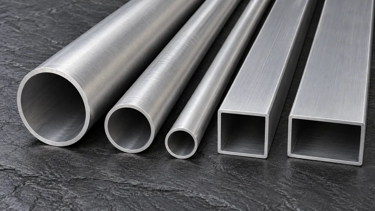
Bending turns straight tube into the elbows, offsets, loops and frames that carry air, fluids and loads around real equipment. Aluminium is chosen because it is light, corrosion-resistant and easy to finish, but it is less forgiving than mild steel: the outside of every bend is stretched and thinned, the inside is compressed and wants to wrinkle, and the round section tries to flatten. Good bent tubing comes from matching alloy, temper, wall thickness, radius and tooling so that none of these effects goes too far.
Three numbers describe any bend. The bend angle is how far the tube turns. The centreline radius (CLR) is the radius measured to the middle of the tube. The D of bend is CLR divided by outside diameter (OD): a 2 in OD tube bent on a 3 in CLR is a 1.5D bend. A fourth number, the wall factor (OD divided by wall thickness), tells the bender how thin-walled the tube is. Tight D and high wall factor together make the hardest bends.
Bent tubes are supplied either as ready-made mandrel bends (a short bend with straight legs that the customer cuts and welds into a system, common in intake, intercooler and exhaust work) or as fully formed parts bent to a CAD drawing with several bends in different planes, as used for frames, handrails, furniture and machine guards.
When a tube bends, its outer fibre must lengthen. A simple geometric estimate of the strain at the outside of the bend is OD ÷ (2 × CLR + OD), or 1 ÷ (2D + 1). The table shows why tight bends are demanding: at 1.5D the outer surface is stretched by about a quarter, which is more than the tensile elongation of many T6 tubes. Mandrel bending succeeds anyway because the mandrel and pressure die apply compressive and supporting forces that move the neutral axis outward and spread the deformation, but the margin is small.
| D of bend (CLR ÷ OD) | Approx. outer-fibre strain | What it means in practice |
|---|---|---|
| 1D | 33 % | Very tight; needs soft temper (O or T4), thick wall and full mandrel tooling |
| 1.5D | 25 % | Tight; achievable in 6061-T6 and 6063 with mandrel and wiper die on suitable walls |
| 2D | 20 % | Common production radius for mandrel-bent T6 tube |
| 3D | 14 % | Comfortable for most alloys; plug mandrel or compression bending may suffice |
| 5D | 9 % | Large radius; suits 7xxx tube and roll bending |
| 10D | 5 % | Sweep or arc; roll bending, no mandrel needed |
Wall thinning follows the same pattern. On the outside of the bend the wall typically thins by roughly the same proportion as the outer-fibre stretch, less the support given by tooling, while the inside wall thickens. For pressure tubes, structural members and parts that will be polished, the thinned outer wall must still meet the design minimum, so specify a minimum wall after bending where it matters.
Strain values are geometric estimates for guidance only. Achievable radii depend on the actual tube, tooling and machine, and should be confirmed by trial bends.
| Alloy and temper | Bendability | Strength | Typical bent-tube uses |
|---|---|---|---|
| 6061-T6 | Good with mandrel at 1.5 – 2D on normal walls; risk of cracking on very tight radii | High (typical UTS 310 MPa) | Intake and intercooler tubes, roll bars, frames, handrails |
| 6061-O / T4 | Very good; tightest radii | Low until aged to T6 after bending | Complex multi-bend parts that are heat-treated later |
| 6063-T5 / T6 | Better ductility than 6061-T6, excellent finish | Medium (typical UTS 186 – 241 MPa) | Architectural and furniture frames, display and lighting structures |
| 3003-O / H14 | Excellent; very formable | Low to moderate | Fuel, oil and coolant lines, HVAC and heat-exchanger tubes |
| 5052-O / H32 | Very good, good fatigue and corrosion resistance | Moderate | Marine and fuel lines, hydraulic and instrument tubing |
| 6082-T6 | Similar to 6061-T6; prefer 2 – 3D or more | High | Structural frames, crash bars, scaffold and load-bearing parts |
| 6005A-T6 | Moderate; suits medium radii | Medium-high | Industrial frames, roof bars, display structures |
| 7005 / 7020 | Limited; generous radii | High, weldable 7xxx | Bicycle frames, sports and fitness equipment |
| 7075-T6 / 7001-T6 | Poor; large radii only (often 5D or more) | Very high | Tent and trekking poles, race and defence components |
6061 versus 6063 for bending: 6061-T6 is about 30 % stronger, which is why most performance mandrel bends are 6061. 6063 bends more easily, cracks less on tight radii and gives a smoother, brighter anodised surface, so it is preferred for visible architectural and furniture tubing where loads are modest.
Bend soft, then harden: heat-treatable alloys can be bent in the O or freshly solution-treated condition and then aged to T6. Bending immediately after solution treatment (the "W" condition) gives excellent formability, but parts must be bent within a short time or refrigerated to delay natural ageing. Full re-heat-treatment after bending can distort complex parts, so fixtures may be needed.
Typical strengths are Aluminum Association / ASM values for the stated tempers; tube specified minimums are set by ASTM B210, B221, B241 or B483 and EN 754/755.
| Process | How it works | Best for | Limitations |
|---|---|---|---|
| Rotary-draw mandrel bending | Tube clamped to a rotating bend die and drawn around it, with an internal mandrel (plug or ball links) and often a wiper die to stop wrinkles | Tight radii (1 – 3D), thin walls, round section that must stay round; CNC multi-bend parts | Dedicated tooling for each OD/CLR; higher cost per bend |
| Rotary-draw without mandrel | As above but no internal support | Thick walls and moderate radii | Ovality and wrinkling on thin walls |
| Compression bending | A roller or wiper shoe presses the tube around a fixed die | Simple bends, furniture, handrails, high volumes | Larger radii, more ovality than mandrel bending |
| Ram / press bending | A ram pushes the tube between two supports | Low-cost bends where appearance is not critical | Significant flattening; not for fluid or precision use |
| Roll bending | Three or more rolls progressively curve the tube | Large radii, arcs, rings and spirals (often 10D and above) | Not for tight radii; ends need straight allowance |
| Stretch bending | Tube or profile is tensioned while wrapped over a form | Extruded profiles and large-radius curves with minimal springback | Specialised equipment, longer set-up |
For fluid systems such as intakes, intercoolers, coolant and fuel lines, mandrel bending is the standard because flattening and wrinkles disturb flow and make sealing harder. For frames, furniture and handrails, compression or rotary-draw bending without a mandrel is usually adequate and cheaper. Square and rectangular tube needs section-specific tooling and is more prone to inner-face buckling, so it is normally bent at larger radii than round tube of the same size.
The table lists widely used 90° mandrel-bend sizes in 16 gauge (0.065 in / 1.65 mm) 6061-T6 tube. Arc length is the length of tube in the bend itself (CLR × angle in radians); add the straight legs to find the cut length. The same OD and CLR combinations are typically offered as 30°, 45°, 60°, 135° and 180° bends.
| OD | CLR | D of bend | Arc length of 90° bend | Approx. outer-fibre strain |
|---|---|---|---|---|
| 0.75 in (19.0 mm) | 1.5 in (38 mm) | 2.00D | 60 mm | 20 % |
| 1 in (25.4 mm) | 1.5 in (38 mm) | 1.50D | 60 mm | 25 % |
| 1 in (25.4 mm) | 2 in (51 mm) | 2.00D | 80 mm | 20 % |
| 1.25 in (31.8 mm) | 2 in (51 mm) | 1.60D | 80 mm | 24 % |
| 1.5 in (38.1 mm) | 2.25 in (57 mm) | 1.50D | 90 mm | 25 % |
| 1.5 in (38.1 mm) | 3 in (76 mm) | 2.00D | 120 mm | 20 % |
| 1.75 in (44.4 mm) | 2.5 in (64 mm) | 1.43D | 100 mm | 26 % |
| 2 in (50.8 mm) | 3 in (76 mm) | 1.50D | 120 mm | 25 % |
| 2 in (50.8 mm) | 4 in (102 mm) | 2.00D | 160 mm | 20 % |
| 2.5 in (63.5 mm) | 3.75 in (95 mm) | 1.50D | 150 mm | 25 % |
| 3 in (76.2 mm) | 4.5 in (114 mm) | 1.50D | 180 mm | 25 % |
| 3.5 in (88.9 mm) | 5.25 in (133 mm) | 1.50D | 209 mm | 25 % |
| 4 in (101.6 mm) | 6 in (152 mm) | 1.50D | 239 mm | 25 % |
| 4.5 in (114.3 mm) | 6.75 in (171 mm) | 1.50D | 269 mm | 25 % |
| 5 in (127.0 mm) | 7.5 in (190 mm) | 1.50D | 299 mm | 25 % |
Many of these sizes are also made in 14 gauge (0.083 in / 2.11 mm) for boosted intake and charge-air systems, structural parts or where thinning must be limited. Metric tubes (for example 25, 32, 38, 50, 63, 76 and 101.6 mm OD) are bent on matching tooling.
| OD | kg/m at 0.065 in (1.65 mm) wall | kg/m at 0.083 in (2.11 mm) wall | Wall factor at 0.065 in |
|---|---|---|---|
| 0.75 in (19.0 mm) | 0.244 | 0.303 | 11.5 |
| 1 in (25.4 mm) | 0.333 | 0.417 | 15.4 |
| 1.25 in (31.8 mm) | 0.422 | 0.530 | 19.2 |
| 1.5 in (38.1 mm) | 0.510 | 0.644 | 23.1 |
| 2 in (50.8 mm) | 0.688 | 0.871 | 30.8 |
| 2.5 in (63.5 mm) | 0.866 | 1.098 | 38.5 |
| 3 in (76.2 mm) | 1.044 | 1.325 | 46.2 |
| 3.5 in (88.9 mm) | 1.222 | 1.552 | 53.8 |
| 4 in (101.6 mm) | 1.400 | 1.779 | 61.5 |
| 5 in (127.0 mm) | 1.755 | 2.233 | 76.9 |
Weights calculated from nominal dimensions and a density of 2.70 g/cm³.
The developed (cut) length of a bent tube is the sum of its straight sections plus the arc length of each bend, measured along the centreline. Arc length equals CLR × bend angle in radians, or CLR × angle ÷ 57.3 when the angle is in degrees.
Example: a 2 in (50.8 mm) OD 6061-T6 tube is bent 90° on a 3 in (76.2 mm) CLR with two 6 in (152.4 mm) legs. The arc is 76.2 × 1.571 = 119.7 mm, so the centreline length is 152.4 + 119.7 + 152.4 = 424.5 mm. The bender then adds a grip allowance at one or both ends, which is trimmed after bending, so the blank is cut longer than this figure.
Aluminium springs back after the bending force is removed, so the tube must be over-bent slightly. Springback grows with yield strength and with radius: a T6 tube bent on a large radius springs back more than an O-temper tube bent tightly. The radius also opens up a little. CNC benders store a correction for each alloy, size and radius, found by trial bends on the first pieces of each batch, which is why first-article inspection matters even for repeat parts.
| Defect | Typical cause | Remedy |
|---|---|---|
| Wrinkles on inner radius | Thin wall, tight radius, no wiper die or mandrel set too far back | Use wiper die, adjust mandrel position, increase radius or wall |
| Ovality (flattening) | Insufficient internal support, soft tube, compression bending | Ball mandrel, better pressure die setting, thicker wall |
| Cracking on outer radius | Temper too hard, radius too tight, surface defects, seam weld on outside | Softer temper or bend-then-age, larger radius, place weld seam at neutral axis |
| Excessive wall thinning | Tight radius, high wall factor, too much drag | Booster on pressure die, larger radius, thicker wall |
| Springback | Elastic recovery after bending, larger in harder tempers | Over-bend allowance set by trial bends; CNC compensation |
| Tool marks | Worn or dry tooling, clamp slippage | Polished tooling, correct lubrication, protective film |
Tolerances should be stated on the drawing. CNC rotary-draw benders typically hold bend angle to about ±0.5° and positions between bends to about ±0.5 – 1 mm on well-set-up jobs; ovality and wall-thinning limits depend on the use and are best agreed per part, with tighter limits for fluid fittings that receive hoses or couplings. Check parts with a bending fixture, coordinate measuring arm or a go/no-go gauge for repeat production.
Clear, black or coloured anodising after bending protects outdoor and decorative parts. 6063 gives the most uniform appearance; 6061 anodises well; 7xxx tube anodises too, though colour can be slightly darker.
Mechanical polishing gives a bright finish for visible intake tubes, medical frames and furniture. Polish after bending, as bending marks the surface.
Durable colour and UV resistance for transport, industrial and outdoor equipment. Clean and pre-treat bends thoroughly.
Beading for hose retention, flaring, swaging, expanding and reducing ends to suit couplings and seals.
Cutting to length, drilling, slotting and punching for brackets and fixings, ideally after bending to keep holes aligned.
TIG and MIG welding of bends into assemblies. With 6061-T6 the heat-affected zone loses strength; use ER4043 or ER5356 filler and design for reduced weld-zone strength or re-heat-treat.
Mandrel bending supports the tube from inside, so it stays round, does not wrinkle and keeps a smooth bore even on 1.5 – 2D radii. Press bending is cheaper but flattens the tube, which restricts flow, makes hose and coupling fits unreliable and looks poor on visible parts.
CLR is the centreline radius of the bend. Divide it by the OD to get the D of bend: 1.5D is a common compact radius, 1D is very tight and needs special tooling and softer tube, and 2 – 3D is easier, cheaper and thins the wall less.
It can if the radius is too tight, the wall too thin or the tooling poorly set. With mandrel tooling 6061-T6 is routinely bent at about 1.5 – 2D. For tighter bends, bend in O or T4 temper and age afterwards, or use 6063.
16 gauge (0.065 in / 1.65 mm) suits most naturally aspirated and moderate-boost systems. 14 gauge (0.083 in / 2.11 mm) or 2 mm metric wall is preferred for high boost, heavy vibration or where the bend will be welded and ported.
Yes. 5052, 6061 and 6082 tubes perform well outdoors, especially when anodised or powder-coated after bending. For boats, use anodised tube and isolate stainless fittings to avoid galvanic corrosion.
Yes. 180° bends can be made with equal or unequal straight legs to your dimensions, within the limits of the bending machine and the clamp length needed between bend and tube end.
Yes, with section-specific tooling. Square and rectangular tubes normally need larger radii than round tube, and custom extrusions need a feasibility check of the section before tooling is made.
Send your drawing or bend data, tube size, alloy and quantity. We will confirm feasibility, tolerances and a delivered price.





