Spring button (snap button)
A spring-loaded button in the inner tube pops through holes in the outer tube. One-handed, fast and cheap; adjustment steps equal the hole pitch. Suits light loads and frequent adjustment.



A square telescopic tube set is a series of square aluminium tubes in which each stage slides inside the next larger one, giving an adjustable length that cannot rotate. Whether the set slides smoothly, rattles or jams is decided by three numbers: the outside size step between stages, the wall thickness and the corner radius. This guide explains how to choose them, which alloys and locking methods suit which loads, and what to put in an enquiry.
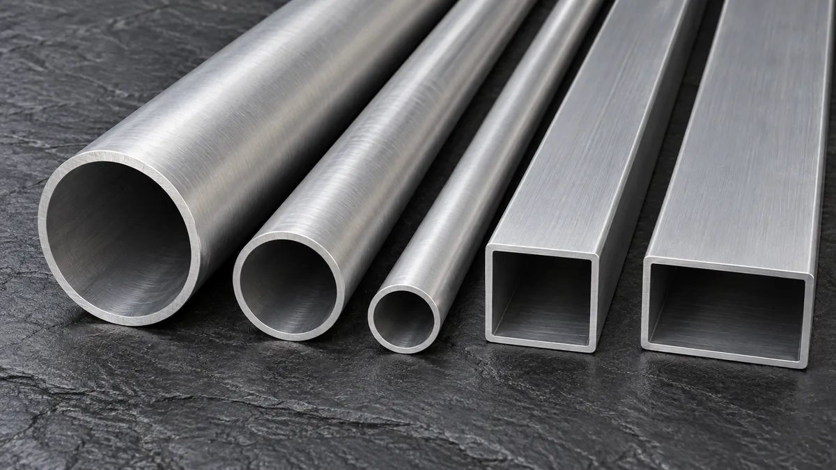
A telescopic (telescoping) tube is two or more tubes of decreasing size that nest inside one another. Pull the inner stage out and the assembly gets longer; push it in and it shortens. A pin, button, clamp or cam then fixes the chosen length. With a square section, the flat faces key the stages against each other, so the assembly cannot twist and holes on different stages stay lined up.
Round telescopic tubes slide and rotate freely, which is ideal for tripod legs, poles and handles that are locked by a twist collar. Square sets are chosen when the extended member must stay oriented: a sign post that has to face the road, a shelf upright with holes that must line up, a machine guard, a medical stand or a lift column carrying a bracket on one face. Square sections are also easier to drill accurately, to bolt to flat plates and to fit with standard angle brackets and connectors.
For a given outside size and wall, a square tube is also stiffer in bending than a round one. A thin-walled square of side b has a second moment of area of roughly (2/3)·b³·t, while a round tube of diameter b has about 0.39·b³·t. That is about 70 % more bending stiffness, for about 27 % more weight per metre. Torsional stiffness of a closed square section is also high, which is why square sets feel solid when a load is hung off one side.
Every telescopic set obeys one relationship. The outside size of the next stage equals the inside size of the stage around it, minus the clearance you want:
ODnext = OD − 2 × t − c, where t is wall thickness and c is the total (two-sided) clearance across the flats.
Rearranged, it tells you the thickest wall a given size step allows: tmax = (step − c) ÷ 2. This single check catches the most common mistake in telescopic designs, which is choosing a standard wall and a standard size step that simply do not fit. A 1/4 in (6.35 mm) step with a 1/8 in (3.18 mm) wall, for example, leaves zero clearance: the next tube is exactly the same size as the hole it is meant to slide into.
| Size step between stages | Total clearance chosen | Maximum wall thickness | Typical use |
|---|---|---|---|
| 3.175 mm (1/8 in) | 0.35 mm (0.014 in) | 1.41 mm (0.055 in) | Light, precise sets: photo, lighting, instruments |
| 4 mm | 1.0 mm | 1.5 mm | General light-duty adjustable frames |
| 5 mm | 0.6 mm | 2.2 mm | Furniture legs, display and lab stands |
| 6 mm | 1.0 mm | 2.5 mm | Medium-duty posts, trolleys, guard frames |
| 6.35 mm (1/4 in) | 0.76 mm (0.030 in) | 2.79 mm (0.110 in) | Pinned posts, sign supports, scaffold-type uprights |
| 10 mm | 1.5 mm | 4.25 mm | Heavy uprights with glide pads |
| 12.7 mm (1/2 in) | 1.5 mm (0.060 in) | 5.6 mm (0.220 in) | Heavy lifting columns, outriggers |
Values are calculated from the nesting rule. Real tubes also carry size tolerances; check that the clearance stays positive with the largest inner tube inside the smallest outer tube.
How much clearance? A tight set (around 0.3 – 0.4 mm total on small sizes) slides with a precise, quiet feel but is sensitive to dents, powder-coat build-up and dirt. A looser set (0.8 – 1.5 mm) tolerates paint and site conditions but needs a positive lock, a clamp or plastic glide pads to stop play. Sets with large size steps commonly use thin UHMW-PE, nylon or acetal wear strips on the inner tube to take up the gap and give a low-friction, non-galling slide.
The tables below are calculated examples, not a catalogue. They show how a set is built once a wall and clearance are chosen; mass per metre is from geometry at 2.70 g/cm³ with sharp corners, so real tubes with corner radii weigh slightly less.
| Stage | Size (mm) | Inside (mm) | Clearance to next stage | kg/m |
|---|---|---|---|---|
| Stage 1 (outer) | 50 × 50 × 1.5 | 47 | 1.0 mm total (0.50 mm per side) | 0.79 |
| Stage 2 | 46 × 46 × 1.5 | 43 | 1.0 mm total (0.50 mm per side) | 0.72 |
| Stage 3 | 42 × 42 × 1.5 | 39 | 1.0 mm total (0.50 mm per side) | 0.66 |
| Stage 4 | 38 × 38 × 1.5 | 35 | 1.0 mm total (0.50 mm per side) | 0.59 |
| Stage 5 | 34 × 34 × 1.5 | 31 | 1.0 mm total (0.50 mm per side) | 0.53 |
| Stage 6 | 30 × 30 × 1.5 | 27 | 1.0 mm total (0.50 mm per side) | 0.46 |
| Stage 7 | 26 × 26 × 1.5 | 23 | Innermost stage | 0.40 |
A 1.5 mm wall with 4 mm steps gives seven stages from 50 mm down to 26 mm with 1 mm total clearance at every joint. That suits a light adjustable stand or exhibition frame. For a heavier column, a thicker wall needs a bigger step:
| Stage | Size (mm) | Inside (mm) | Clearance to next stage | kg/m |
|---|---|---|---|---|
| Stage 1 (outer) | 80 × 80 × 2.5 | 75 | 1.0 mm total (0.50 mm per side) | 2.09 |
| Stage 2 | 74 × 74 × 2.5 | 69 | 1.0 mm total (0.50 mm per side) | 1.93 |
| Stage 3 | 68 × 68 × 2.5 | 63 | 1.0 mm total (0.50 mm per side) | 1.77 |
| Stage 4 | 62 × 62 × 2.5 | 57 | 1.0 mm total (0.50 mm per side) | 1.61 |
| Stage 5 | 56 × 56 × 2.5 | 51 | Innermost stage | 1.44 |
Here a 2.5 mm wall with 6 mm steps gives five stages from 80 mm to 56 mm, again with 1 mm total clearance. Note how quickly the sizes shrink: every extra stage costs one size step, so a long multi-stage reach with a strong innermost tube needs either a large outer tube or fewer stages.
Corner radius causes more telescopic problems than any other dimension. The inside corner radius of a tube is roughly its outside radius minus the wall thickness. If the inner tube has a sharper outside corner than the inside corner of the outer tube, the inner tube touches in the corners before the flats, and the clearance you calculated across the flats never appears.
Extruded aluminium square tube is normally supplied to the dimensional tolerances of EN 755-8 (porthole tubes) or ANSI H35.2 / ASTM B221, which cover size, wall, corner radius, straightness and twist. For telescopic use it is worth stating that stages must slide over the full length, and asking for sample lengths to be test-fitted before the full order is cut.
Most telescopic sets are extruded from 6xxx alloys, which extrude accurately into thin walls with good surface quality and accept anodising. 7xxx alloys are used where weight is critical. Minimum strengths below are typical published minimums for extruded tube; the exact values depend on standard, section and wall, and are confirmed on the mill certificate.
| Alloy and temper | Strength level | Strengths | Watch-outs | Typical telescopic use |
|---|---|---|---|---|
| 6063-T5 / T6 | Moderate (T6 typical about 240 MPa tensile) | Best surface and anodising, tight extrusion tolerances, low cost | Softer faces dent and wear; use glide pads under load | Furniture, display, lighting, medical stands |
| 6061-T6 | Higher (ASTM B221 minimum 260 MPa tensile, 240 MPa yield) | Good all-round strength, machining and corrosion resistance | Less sharp corners and slightly rougher surface than 6063 | Pinned posts, sign supports, frames |
| 6005A-T6 | Higher, close to 6061 in thin hollow sections | Extrudes thin, complex hollows well; good weldability | Less widely stocked outside Europe | Structural uprights, platforms, rail interiors |
| 6082-T6 | Highest common 6xxx (EN 755-2 hollow profiles, minimum about 290 MPa tensile) | Strong, good corrosion resistance | Harder to extrude thin walls with fine finish | Heavy columns, outriggers, scaffold parts |
| 7005 / 7001-T6 | High to very high | Light, stiff stages for sport and outdoor gear | Higher cost; check stress-corrosion guidance for 7xxx | Tent and trekking frames, adjustable sports equipment |
| 7075-T6 | Very high (typical about 570 MPa tensile) | Maximum strength per weight | Poor weldability; anodise or coat for outdoor use | Lightweight masts, high-load compact sets |
A practical choice for most industrial sets is 6061-T6 or 6005A-T6 for loaded stages and 6063-T5/T6 for light, appearance-critical sets. Where the outer stage takes most of the bending and the inner stages are short, some designs mix alloys, but keep corner geometry and tolerances matched across the set. For alloy background see the 6061 square tube and 6063 square tube pages.
A spring-loaded button in the inner tube pops through holes in the outer tube. One-handed, fast and cheap; adjustment steps equal the hole pitch. Suits light loads and frequent adjustment.
A through-pin, detent pin or gravity pin passes through aligned holes in both stages. Simple, positive and strong in shear; the standard for sign posts, scaffold-type uprights and outriggers.
A collar on the outer tube squeezes the inner tube at any position. Gives infinite adjustment without drilling the inner stage, but holding force depends on clamping and friction.
A threaded knob presses a pad against the inner tube through a nut on the outer stage. Stepless and cheap; best for light loads, since the pad can slip or mark the surface.
A moulded collar or latch on the end of the outer tube both locks and guides the inner tube, removing metal-to-metal contact and noise. Common in furniture and photo gear.
Bolts clamp or pass through both stages for semi-permanent settings in vibrating or heavy-duty structures.
Pre-drilled (perforated) square tubes, often with holes on all four faces at a regular pitch, turn a telescopic set into a modular system: the same tube accepts pins at any height and brackets on any face. When specifying perforated tube, state hole diameter, pitch, the faces to be drilled, and the position of the first hole from the end, so holes line up between stages. See also perforated aluminium tube.
The overlap is the length of the inner stage that stays inside the outer stage at full extension. When a telescopic member carries a side load, the joint acts like a short lever: the bending moment at the joint is resisted by two contact forces at either end of the overlap. Their size is roughly the moment divided by the overlap length, so halving the overlap doubles the bearing force on the tube walls.
This is general guidance. Scaffolds, access equipment, lifting devices and structures carrying people must be designed and verified to the applicable code by a qualified engineer.
Telescopic sets are only as good as their machining. Cut ends square and deburr inside and out, because an internal burr on the outer tube catches the inner stage. Drill or punch holes on a jig so hole positions repeat between stages. Typical secondary operations include:
Anodising is usually the better finish for sliding stages because it adds little thickness and resists wear. Powder coating is tougher against impact and gives more colour options, but a coat on both sliding faces can consume a tight clearance entirely. A common compromise is to powder-coat the outer stage and anodise the inner stages.
| Sector | Typical items | Usual set-up |
|---|---|---|
| Construction and site support | Adjustable props, formwork supports, temporary barriers | Thicker walls, pin-and-hole locking, 6061-T6 or 6082-T6 |
| Signage and traffic | Portable sign stands, height-limit frames, guide posts | Four-face perforated tube, pins, base plates |
| Furniture and exhibition | Height-adjustable desk and table legs, display frames, shelf uprights | 6063-T5/T6, plastic glides, spring buttons or clamp knobs |
| Photo, film and lighting | Light stands, camera arms, backdrop supports | Thin walls, tight clearance, cam or clamp locks |
| Medical and laboratory | IV stands, mobile instrument carts, adjustable frames | Anodised 6063 or 6061 for cleanability |
| Industrial and automation | Adjustable guards, sensor mounts, conveyor supports | 6061-T6 or 6005A-T6, clamp or pin locking |
| Transport and outdoor | Trailer outriggers, awning arms, tent and camping frames | 6082-T6 for heavy duty; 7xxx for light outdoor gear |
For round-section sets and a broader overview of telescopic tubing, read our telescopic tube guide, which covers round and square sets together.
| Factor | Square telescopic tube | Round telescopic tube |
|---|---|---|
| Rotation | Locked by the section shape | Free to rotate unless keyed |
| Bending stiffness (same size and wall) | About 70 % higher | Lower |
| Weight per metre (same size and wall) | About 27 % higher | Lower |
| Typical locking | Pins, spring buttons, clamp collars, brackets | Twist locks, cam collars, spring buttons |
| Fit sensitivity | Corner radius and twist must be controlled | Only diameter and ovality |
| Mounting | Flat faces bolt directly to plates and brackets | Needs clamps or saddles |
| Typical uses | Posts, uprights, frames, carts, guards | Poles, tripod legs, handles, masts |
A rectangular telescopic set offers the same anti-rotation benefit with extra stiffness in one direction, useful for outriggers loaded mainly in one plane. Oval sets give a softer appearance and some anti-rotation; see oval aluminium tubing.
Metline supplies square aluminium tube for telescopic sets in standard and custom sizes, cut to length and machined to drawing on request, with delivery worldwide on EXW, FOB, CIF or DAP terms. Locking hardware, plastic glides and brackets are normally sourced by the assembler; we focus on the aluminium tube stages.
Total clearance across the flats (both sides together) is usually about 0.3 – 0.4 mm for small, precise sets and 0.8 – 1.5 mm for larger or painted sets. Tighter fits feel better but jam with dents, dirt or coating build-up; looser fits need glide pads or a positive lock.
Subtract twice the wall thickness and the clearance from the outer tube's outside size. A 50 × 1.5 mm outer tube has a 47 mm inside, so with 1 mm clearance the next stage is 46 mm.
Usually the corner radius. If the inner tube's outside corners are sharper than the outer tube's inside corners, the tubes touch at the corners first. Twist or bow along the length is the other common cause.
6063-T5/T6 gives the best surface and tolerances for light sets; 6061-T6 and 6005A-T6 are the usual choice for loaded posts and frames; 6082-T6 suits heavy columns; 7xxx alloys are used for very light outdoor and sports equipment.
Yes, but a typical powder coat adds about 60 – 120 µm per surface, which can use up a tight clearance. Anodise sliding stages, mask the sliding faces, or design the clearance to include the coating.
Yes. Send the dimensions of your existing stage, ideally including corner radius, and we will check the fit before supplying the matching aluminium tube.
Send the stage sizes or the reach, load and number of stages. We will check the nesting fit and reply with aluminium tube options and delivery to your site.





