Overlap length
The engaged length of two stages carries the bending moment as a couple. A common starting point is an overlap of at least 2 – 3 times the inner tube OD, more for long, heavily loaded masts.



Telescopic tubing is a set of tubes sized so that each one slides inside the next, letting a pole, mast or support extend and collapse. Getting it right depends on three numbers: outside diameter, wall thickness and the clearance between them. This guide gives nesting charts for round and square aluminium tube, explains how to choose alloy, temper and locking method, and lists what to specify when ordering. Metline supplies telescoping aluminium tube sets cut to length and machined to drawing, worldwide.
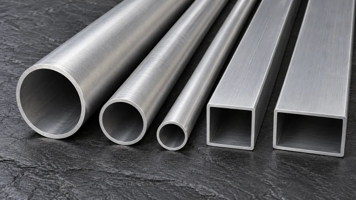
In a telescoping set, the inside diameter of each tube is slightly larger than the outside diameter of the next smaller tube. The difference is the sliding clearance. Too little, and the tubes bind when dirty, cold or slightly bent; too much, and the assembly wobbles and the lock has to work harder to hold it rigid.
Aluminium is the natural material for most telescoping products because weight matters at full extension: every gram at the tip of a long pole is felt as bending moment at the user's hands or at the base clamp. Aluminium tube is about one third the weight of a steel tube of the same size, does not rust in the sliding joint, takes a hard anodised wear surface and is easily drilled, slotted and swaged for locks.
Telescoping tube is made in two ways. Cold drawn tube is pulled through a die over a plug, giving tight diameter and wall tolerances and a smooth bore, which is ideal for close-fitting round sets. Extruded tube is pushed through a die and is the economical route for larger sizes and for square, rectangular, oval and custom profiles, where matching dies are designed as a nesting family.
The best-known round series uses outside diameters in 1/8 in (0.125 in) steps. The inside diameter of a tube is OD minus twice the wall, so the clearance to the next size down is 0.125 in minus twice the wall. With a 0.058 in wall the clearance is 0.009 in (about 0.23 mm) on diameter, a close sliding fit. With a 0.049 in wall it is 0.027 in (about 0.69 mm), a free fit that tolerates dirt and paint. The chart is calculated from that geometry.
| OD (in) | OD (mm) | ID at 0.058 in wall (in) | ID at 0.049 in wall (in) | Next tube OD (in) | Mass at 0.058 in wall (kg/m) |
|---|---|---|---|---|---|
| 0.250 | 6.3 | 0.134 | 0.152 | — | 0.061 |
| 0.375 | 9.5 | 0.259 | 0.277 | 0.250 | 0.101 |
| 0.500 | 12.7 | 0.384 | 0.402 | 0.375 | 0.140 |
| 0.625 | 15.9 | 0.509 | 0.527 | 0.500 | 0.180 |
| 0.750 | 19.0 | 0.634 | 0.652 | 0.625 | 0.220 |
| 0.875 | 22.2 | 0.759 | 0.777 | 0.750 | 0.259 |
| 1.000 | 25.4 | 0.884 | 0.902 | 0.875 | 0.299 |
| 1.125 | 28.6 | 1.009 | 1.027 | 1.000 | 0.339 |
| 1.250 | 31.8 | 1.134 | 1.152 | 1.125 | 0.378 |
| 1.375 | 34.9 | 1.259 | 1.277 | 1.250 | 0.418 |
| 1.500 | 38.1 | 1.384 | 1.402 | 1.375 | 0.458 |
| 1.625 | 41.3 | 1.509 | 1.527 | 1.500 | 0.497 |
| 1.750 | 44.4 | 1.634 | 1.652 | 1.625 | 0.537 |
| 1.875 | 47.6 | 1.759 | 1.777 | 1.750 | 0.577 |
| 2.000 | 50.8 | 1.884 | 1.902 | 1.875 | 0.616 |
| Wall | Diametral clearance with 1/8 in OD steps | Fit |
|---|---|---|
| 0.058 in (1.47 mm) | 0.009 in (0.23 mm) | Close sliding fit; good alignment, needs clean tubes |
| 0.049 in (1.24 mm) | 0.027 in (0.69 mm) | Free fit; tolerant of paint and grit, a little more play |
| 0.035 in (0.89 mm) | 0.055 in (1.40 mm) | Loose; usually needs bushings or collars |
Metric sets work the same way. For example, 2 mm OD steps with a 0.9 mm wall leave 0.2 mm clearance; 3 mm steps with a 1.2 mm wall leave 0.6 mm. Tolerances on OD and wall consume part of the clearance, so check worst-case fits.
Square tube telescopes the same way, with one complication: the corners. The outside corner radius of the inner tube must be smaller than the inside corner radius of the outer tube, or the tubes touch at the corners while the flats are still loose. Square sets are therefore usually designed with more clearance than round sets, and the extrusion dies for a family are drawn together so corner radii step down consistently.
| Wall | Outside size step | Clearance across flats | Clearance per side |
|---|---|---|---|
| 0.040 in (1.0 mm) | 0.125 in (3.2 mm) | 0.045 in | about 0.022 in (0.57 mm) |
| 0.065 in (1.65 mm) | 0.250 in (6.35 mm) | 0.120 in | about 0.060 in (1.52 mm) |
| 0.083 in (2.1 mm) | 0.250 in (6.35 mm) | 0.084 in | about 0.042 in (1.07 mm) |
| 0.105 in (2.67 mm) | 0.250 in (6.35 mm) | 0.040 in | about 0.020 in (0.51 mm) |
| 0.125 in (3.18 mm) | 0.250 in (6.35 mm) | 0.000 in | no fit; needs a larger step |
Values are calculated as size step minus twice the wall. Square sets with generous clearance commonly use plastic wear pads, shims or nylon slide strips at the overlap to remove play while keeping the slide smooth. For a dedicated treatment of multi-stage square systems, see our square telescopic tube guide.
| Alloy / temper | Typical tensile / yield | Form | Best for |
|---|---|---|---|
| 6061-T6 | 310 / 276 MPa | Drawn and extruded | General telescoping poles, tripods, masts, equipment supports |
| 6063-T6 / T5 | 241 / 214 MPa (T6) | Extruded | Square and custom profiles where surface finish and anodising matter more than strength |
| 6005A-T6 | EN 755-2 min. 270 / 225 MPa (wall ≤ 5 mm) | Extruded | Larger extruded round and multi-shape sets |
| 7005-T6 | higher than 6061-T6 | Extruded | Lighter, stronger outdoor and sports structures; weldable 7xxx grade |
| 7075-T6 | 572 / 503 MPa | Drawn | Thin-wall, high-stress sections: trekking poles, ski poles, premium tent and camera poles |
Typical values from Aluminum Association / ASM data except where minimums are stated; actual values for each lot are on the mill certificate.
Stiffness, not strength, often limits a long telescoping pole. All aluminium alloys have nearly the same modulus (about 69 – 72 GPa), so a stronger alloy will not reduce deflection; a larger diameter or longer overlap will. Choose 7075 when you need thin walls to survive high bending stress, and 6061 when cost, machinability and corrosion resistance matter most.
The engaged length of two stages carries the bending moment as a couple. A common starting point is an overlap of at least 2 – 3 times the inner tube OD, more for long, heavily loaded masts.
Thin walls (about 1.0 – 1.65 mm) suit hand-held poles and light supports; 2.5 – 3.2 mm walls suit equipment stands and masts carrying loads at the tip.
Even a small bow eats clearance and causes binding at full extension. Specify straightness for long lengths and avoid heavy machining on one side of thin tube.
Hard anodising (Type III) gives a wear-resistant sliding surface; clear Type II anodising is enough for occasional adjustment. Remember the coating adds to diameter.
Outer tubes and inner tubes of the same alloy expand equally, so fits do not change with temperature. Avoid steel inner parts in wet service unless isolated.
Calculate the worst case: largest inner OD against smallest outer ID, including coating thickness. Drawn tube to ASTM B210 holds much tighter limits than extruded tube.
| Lock type | How it works | Tube preparation |
|---|---|---|
| Spring (snap) button | A spring-loaded button in the inner tube snaps into holes in the outer tube | Accurately spaced holes along the outer tube; one hole in the inner tube |
| Pin lock | A removable pin passes through aligned holes in both tubes | Matched hole patterns; often used on heavy-duty stands |
| Twist (cam or expander) lock | Rotating the tubes expands a plug inside the outer tube | Clean bore, consistent ID; no holes |
| Lever (flip) clamp | An external collar clamps the outer tube onto the inner one | Slotted end on the outer tube; fit tolerance matters |
| Collet or screw clamp | A threaded collar compresses a split collet | Threaded or swaged end; common on camera and survey poles |
Spring-button systems give fixed positions and are the simplest; twist and lever locks give infinite adjustment but depend on consistent wall and ID. Lock hardware is normally sourced by the assembler; Metline supplies the aluminium tube cut to length with holes, slots and end forming done to drawing.
Suppose a hand-held inspection pole must reach about 3 m and collapse to about 1.1 m. Three stages of 1.15 m each, with 100 mm overlaps, give an extended length of roughly 3.25 m. Starting from a comfortable grip of 1.250 in (31.75 mm) OD for the bottom stage and using the 1/8 in rule with a 0.058 in wall, the middle stage is 1.125 in OD and the top stage 1.000 in OD. Each joint has 0.009 in diametral clearance, enough for a smooth slide with clean, clear-anodised tube.
Using the chart, the three tubes weigh about 0.38, 0.34 and 0.30 kg per metre, so the tube in the finished pole weighs roughly 1.2 kg before locks, grips and end caps. If testing shows too much tip deflection, the efficient fix is to move every stage up one or two sizes rather than to change from 6061-T6 to 7075-T6, because the stiffness of all aluminium alloys is almost identical. If the slide feels tight after anodising, switch the inner stages to the 0.049 in wall, which opens the clearance to 0.027 in at the cost of a little more play.
Masses calculated from geometry at 2.70 g/cm³. A short prototype set is the quickest way to confirm feel and lock function before ordering production quantities.
| Application | Typical shape | Typical alloy |
|---|---|---|
| Painting, window-cleaning and extension poles | Round or oval | 6061-T6, 6063 |
| Survey, measuring and inspection poles | Round, sometimes oval | 6061-T6 |
| Camera tripods, light stands, monopods | Round | 6061-T6, 7075-T6 |
| Antenna and telescopic masts | Round or multi-sided | 6061-T6, 6005A-T6 |
| Medical aids: crutches, walkers, IV stands | Round | 6061-T6 |
| Equipment stands and adjustable supports | Square or rectangular | 6061-T6, 6063-T6 |
| Trekking poles, boat hooks, flagpoles | Round | 7075-T6, 6061-T6 |
| Tents, awnings and shelters | Round | 7001, 7075, 6061 (see tent pole tube) |
With outside diameters in 1/8 in steps, a 0.058 in wall gives a close 0.009 in diametral clearance and a 0.049 in wall gives a freer 0.027 in clearance. Both are standard telescoping combinations.
For small round drawn tubes, about 0.2 – 0.4 mm on diameter gives a smooth, low-play slide. Larger or extruded tubes, square tubes and coated tubes need more, often 0.5 – 1.5 mm, with wear pads to take up play.
6061-T6 is the default for its balance of strength, cost and corrosion resistance. 7075-T6 is used for thin-wall, high-stress poles such as trekking and camera poles; 6063 suits square and decorative profiles.
Usually because the corner radii of the inner and outer tubes conflict, or the tubes are bowed. The inner tube corners must be tighter than the outer tube inside corners, and long lengths need a straightness limit.
Yes, and it is recommended so holes and cut ends are protected. Allow for the coating thickness on both sliding surfaces when you set the clearance.
No. We supply the aluminium tube stages cut to length and machined to drawing, with anodising on request. Lock hardware, grips and final assembly are done by the product maker.
Send the stage sizes, lengths, alloy, finish and quantities. We will reply with a fit check, availability and a delivered price.





