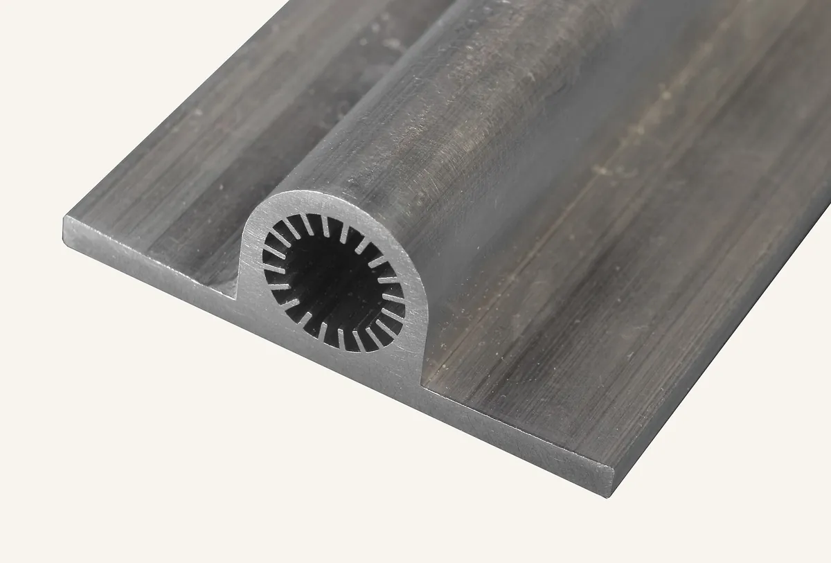
Microchannel (multi-port) aluminium tube is extruded through porthole dies that form dozens of parallel channels with walls only a few tenths of a millimetre thick. Whether a section can be produced reliably depends far more on the die than on the press, so tooling decides yield, leak-tightness and brazing success. This guide explains how the dies work, which sizes and alloys are common, and how to move from drawing to qualified samples with the least risk.
A microchannel tube, also called a multi-port extrusion (MPE) or parallel-flow tube, is a flat aluminium tube divided internally into a row of small rectangular, round or triangular channels. It is the core element of parallel-flow condensers, evaporators, heat-pump coils, gas coolers and liquid cooling plates for battery packs and power electronics.
Extruding a flat tube with a single cavity is routine. Extruding a 25 mm wide tube with sixteen channels, an outer wall of about 0.3 mm and internal webs of similar thickness is not. The metal must fill every channel at the same speed, weld back together cleanly behind each mandrel bridge and leave the die with every web intact and every wall within a few hundredths of a millimetre. If one channel runs fast or slow, the tube bows, twists or tears a web; if the weld seams are weak, the tube may pass a dimensional check and then leak after brazing or pressure cycling.
Because of this, buyers of microchannel tube spend most of their qualification effort on the die. A proven die that has already run in volume brings a known yield, known dimensional capability and a history of passing burst and brazing tests. A new die, even when well designed, normally needs one or more correction rounds before the section runs consistently. Understanding how the tooling works helps engineers write realistic drawings, choose between an existing die and new tooling, and set up a sensible validation plan.
Die design
How a porthole die forms a multi-port tube
Microchannel tube is made with a porthole die, sometimes called a bridge or hollow die. It has two main parts. The upper part (the mandrel or die holder) contains several feed ports separated by bridges, and carries a row of small mandrel tips, one for each channel. The lower part (the die plate or cap) contains the outer opening that shapes the tube exterior. Hot aluminium from the billet is split into separate streams by the ports, flows around the bridges, and recombines in a welding chamber just ahead of the bearing surfaces. Under very high pressure and temperature the streams bond in the solid state, then pass between the mandrel tips and the die cap to form the walls and webs.
Die feature
What it controls
Typical design concern
Feed ports and bridges
How much metal reaches each part of the section
Balancing flow so outer channels do not lag the centre
Welding chamber
Quality of the longitudinal weld seams
Enough depth and pressure for a sound solid-state weld
Mandrel tips
Shape and size of each channel
Strength of very slender tips that can deflect or break
Bearing lengths
Local exit speed of the metal
Adjusted channel by channel to equalise flow
Die cap opening
Outer width, height, corner radii and crown
Compensating for elastic deflection under load
Backer and bolster support
Overall die stiffness
Preventing die deflection on wide sections
Die steels are hot-work tool steels of the H13 family (1.2344, SKD61 or equivalent), hardened and tempered and then nitrided on the bearing surfaces to resist wear and aluminium pick-up. The webs of a microchannel tube are so thin that the mandrel tips are among the most fragile features in extrusion tooling. Designers use generous radii where tips join the mandrel body, careful port geometry so pressure is evenly shared, and bearing lengths that are corrected in very small steps during die trials.
Flow balance is the central problem. Metal naturally moves faster through the centre of the section and slower at the edges and through thin areas. A section with thick outer walls and thin webs, or with channels of different sizes, is harder to balance. Die makers correct this by changing port areas, adding pockets or choke angles and altering bearing lengths, which is why a die often needs trial pressings and corrections before the profile runs straight and within tolerance.
Section families
The three size bands for microchannel and cooling-plate extrusions
Tooling for multi-port tube falls naturally into three width bands. Each band has different applications, alloys and design risks, and buyers should know which band their section falls into before discussing tooling.
Width band
Typical height
Typical channel count
Common alloys
Main applications
Up to about 60 mm
About 1.3 – 10 mm
3 – 20 or more
1xxx, 3xxx
Automotive condensers and evaporators, HVAC coils, heat-pump heat exchangers, radiators
Battery cooling plates and multi-cavity cooling channels, energy-storage system cooling
Over about 253 mm
Varies with design
Many, often in zones
3xxx, 6xxx
One-piece battery trays and large cooling plates, often produced by joining two or more extrusions
Bands and ranges are indicative of sections commonly extruded in the market; the feasible combination of width, height, wall and channel count depends on the specific die and press.
Narrow flat tubes (≤ 60 mm)
The classic condenser and evaporator tube. Walls of about 0.25 – 0.4 mm and very small channels give a high internal surface area. The main risks are web breakage, port collapse and wall-thickness variation. Tubes are usually extruded onto coils and later straightened and cut.
Wide multi-cavity profiles (60 – 253 mm)
Used where one wide extrusion replaces several narrow tubes, which removes joints and leak points. Flatness and edge stability become the main concerns, because a wide thin section can bow, dish or curl at the edges as it cools. Die support and flow balance across the width are critical.
Ultra-wide sections (> 253 mm)
Beyond the width a single die can form, designers either use very large presses and dies or join several extrusions by friction stir welding, laser welding or brazing. Joint design, overall flatness and the pressure capability of the joined seams then control the result.
Material choice
Which aluminium alloys are used for microchannel tube
Alloy choice for multi-port tube is a balance between extrudability, strength after brazing, corrosion behaviour and thermal conductivity. Very thin webs need an alloy that flows easily through the die at reasonable pressure, which is why low-alloyed grades dominate.
Alloy family
Examples
Strengths
Limitations
Typical use
Commercially pure (1xxx)
1050, 1100, 1197
Easiest to extrude thin webs; high thermal conductivity
Lowest strength; corrosion relies on surface protection
Condenser and evaporator tubes
Low-manganese 3xxx
3102
Excellent extrudability with a modest strength gain
Lower strength than 3003
Mainstream condenser tube, often zinc-coated
3003 and modified 3xxx
3003, long-life 3xxx variants
Higher post-braze strength and better pitting behaviour
Higher extrusion pressure, harder on thin dies
Heat-pump and higher-pressure tubes, cooling plates
6xxx structural
6063, 6061
Much higher strength and stiffness; heat-treatable
Less suited to brazing (magnesium interferes with flux brazing)
Wide cooling plates and battery trays joined by welding or adhesive
Corrosion protection is usually added rather than built into the alloy. The most common method is zinc arc spray applied in line as the tube leaves the press. During brazing the zinc diffuses into the surface and creates a layer that is less noble than the core, so corrosion spreads sideways along the surface instead of pitting through the wall. Coating weights of a few grams per square metre are typical, and the exact value is agreed with the heat-exchanger maker. Alternatives include pre-flux coatings that combine flux and binder (sometimes with silicon powder) so the bare tube can be brazed to unclad fins.
If your system runs on high-pressure refrigerants such as R744 (CO2), expect thicker webs, smaller or rounder ports and a stronger alloy, because burst requirements are several times higher than for conventional refrigerants. The alloy, tube geometry and test pressures need to be fixed together, not separately.
Tooling route
Using an existing die or ordering new tooling
The fastest and lowest-risk route to samples is to match your design to a die that already exists and has run in production. Many condenser and cooling-plate sections are close enough to an existing die that a heat-exchanger designer can adapt the core around it. Where the section is genuinely unique, a new die is designed, cut and trialled.
Factor
Existing proven die
New die
Tooling cost
Usually none or a small trial charge
Full die design and manufacture cost
Time to first samples
Shortest: trial pressing can start once billet and press time are arranged
Longer: design, machining, heat treatment, nitriding and correction rounds
Yield and stability
Known from previous production
Unknown until trial and correction are complete
Design freedom
You adapt the core to the tube
The tube is optimised for your core
Best for
Prototypes, feasibility studies, early pressure and brazing tests
Volume programmes with fixed geometry or special performance targets
A common practical approach is to start with samples from the nearest existing section, build prototype cores, run pressure, thermal and brazing tests, and only then commit to a dedicated die if the programme needs a different geometry. This avoids paying for tooling before the heat-exchanger concept is proven. When you contact Metline, send the drawing or target dimensions and we will confirm whether the section can be supplied from existing tooling or needs a new die.
Dimensional control
Typical tolerances and what they affect
Microchannel tube is held to much tighter tolerances than general extrusions, because each tube must slide into a header slot, braze to fins along its full length and hold pressure. General extrusion tolerance standards such as EN 755-9 and ANSI H35.2 do not cover these sections well, so tolerances are agreed on the drawing. The table shows values that are frequently specified for narrow condenser tubes; wide cooling plates use looser figures scaled to their width.
Characteristic
Frequently specified value (narrow tube)
Why it matters
Outer width
About ±0.05 mm
Header slot fit and braze gap
Outer height
About ±0.05 mm
Fin contact and core stack height
Wall and web thickness variation
About ±0.03 mm or tighter
Burst pressure and post-braze strength
Straightness (camber)
About 0.2 – 0.5 mm per metre
Automatic core assembly and fin alignment
Twist
Agreed per length
Tube insertion into header slots
Crown (flatness across width)
Agreed on drawing
Full contact between tube and fin
Cut length
About ±0.5 mm or tighter for cut tubes
Header-to-header fit
These are typical engineering values, not standard limits. Confirm tolerances on the drawing and on the inspection plan before tooling is committed.
For wide cooling-plate extrusions, the critical tolerances shift to flatness over the full width, edge straightness and the position of internal ribs, because the plate must sit fully against battery cells or electronic modules. Flatness is affected by die design, cooling at the press exit and stretching, so it should be discussed during die design rather than left to final inspection.
Validation
How microchannel samples are tested
Samples are only useful if they prove the tube will survive brazing and service. A sensible validation plan covers the extrusion itself, the brazed joint and the finished core.
Section checkCut cross-sections and measure every wall and web with an optical profile projector or vision system. Check for incomplete channels, collapsed webs and burrs.
Weld seam checkEtch cross-sections and examine the longitudinal weld lines to confirm a continuous, sound bond with no lines of oxide or voids.
Burst and pressure testsPressurise sealed tube lengths with water or oil until failure to establish burst pressure, and run pressure-cycle tests at the system operating pressure.
Leak testsHelium or air-under-water leak testing on tubes and on brazed sample cores to confirm hermeticity.
Brazing trialsBraze tube, fin and header samples in your own controlled-atmosphere or vacuum furnace to confirm wetting, fillet formation and joint strength.
Corrosion testsSalt spray (ASTM B117) or acidified synthetic seawater (SWAAT, ASTM G85 Annex A3) on brazed cores to compare corrosion life with the target.
Agree the test pressures, number of samples and acceptance criteria with the extruder before the first trial so results can be compared against a fixed specification. Keeping one set of retained samples from each trial is also good practice when the die is later corrected.
Preparation for assembly
Cutting, forming and surface preparation
Straightening and cutting
Coiled tube is straightened and cut to length with fly-cut or rotary cutting that leaves a clean, burr-free end. Burrs and crushed ports at the cut end are a common cause of blocked channels and brazing defects.
Bending and twisting
Narrow tubes can be bent on edge or flat, and twisted for serpentine evaporators. Bend radii depend on alloy and wall; tight bends risk web collapse, so radii should be trialled early.
Machining of wide profiles
Cooling plates often need end milling, port drilling, datum holes and reference edges so manifolds and fittings can be welded or brazed on in the right position.
Zinc coating
Arc-sprayed zinc for sacrificial corrosion protection after brazing; coating weight and coverage are specified on the drawing.
Pre-flux coating
Flux applied with a binder, sometimes with silicon powder, so the tube can be brazed without separate flux spraying or with unclad fin stock.
Cleanliness
Low residual oil and oxide on the surface, because contamination interferes with flux wetting and leaves voids in brazed joints.
Typical specifications
Typical tube specifications by application
The examples below describe the kind of sections commonly requested. They are written generically to show how geometry, alloy and testing are combined; your own design will differ.
Application
Typical section
Alloy and surface
Key acceptance tests
Passenger-car condenser or heat pump
About 16 – 32 mm wide, 1.3 – 2 mm high, 10 – 20 channels, walls about 0.3 mm
About 150 – 250 mm wide, thin multi-cavity section
3xxx or 6xxx
Flatness over width, joint leak test after manifold welding
A typical narrow condenser tube of about 25 × 2 mm with sixteen channels and walls near 0.3 mm illustrates the difficulty: the outer width might be held to about ±0.05 mm and wall variation to a few hundredths of a millimetre, while every channel must remain open and every seam pass brazing and leak tests. A typical battery cooling channel of about 120 × 6 mm, by contrast, uses heavier walls of around 1.5 mm and reinforcing ribs, and the hardest requirement becomes flatness rather than wall thickness.
Ordering
What to send when you request microchannel tube or tooling
GeometryDrawing or target dimensions: width, height, wall and web thickness, channel shape and count, corner radii and tolerances.
MaterialAlloy and temper, surface condition (bare, zinc-sprayed, pre-fluxed) and any corrosion requirement.
PerformanceRefrigerant or coolant, operating and burst pressures, brazing method (CAB or vacuum) and any customer test standard.
Supply formCoils or cut lengths, cut-length tolerance, end condition, machining and packing requirements.
ProgrammeSample quantity, expected volumes and destination, so the tooling route and delivery terms (EXW, FOB, CIF or DAP) can be agreed.
Each delivery carries a mill test certificate to EN 10204 3.1 with the chemical analysis and test results for the lot, and export packing designed to protect thin-wall tube from crushing and moisture.
Related products & guides
Related microchannel, brazing and cooling-plate pages
For the tube itself, the brazing materials around it and other heat-exchanger tube types, see:
What kind of die is used to extrude microchannel tube?
A porthole (bridge) hollow die. The metal is split into streams by feed ports, flows around bridges that hold the mandrel tips, and re-welds in a welding chamber before the die cap forms the outer shape. Each mandrel tip forms one channel.
How thin can the walls of a microchannel tube be?
Narrow condenser tubes are commonly extruded with outer walls and webs of roughly 0.2 – 0.4 mm. The practical minimum depends on alloy, channel size, tube width and die design; very thin webs are easiest in 1xxx and 3102 alloys.
Can I get samples without paying for a new die?
Often, yes, if your section is close to a die that already exists. Samples from an existing die let you test brazing, pressure and fit before deciding whether a dedicated die is worth the cost.
Which alloy is best for aluminum microchannel tube?
1xxx and 3102 are the standard choices for condenser and evaporator tubes because they extrude easily and braze well, usually with zinc arc spray for corrosion protection. 3003 and modified 3xxx alloys suit higher pressures; 6063 or 6061 suits wide cooling plates that need stiffness and are joined by welding.
Why do new microchannel dies need correction?
Metal flow through a multi-port die is hard to predict exactly. Trial pressings show which channels run fast or slow, and the die maker adjusts bearing lengths and ports until the tube runs straight, flat and within tolerance.
What tests should microchannel samples pass?
Cross-section measurement, weld seam examination, burst and pressure-cycle testing, leak testing, brazing trials in your furnace and, for long-life applications, SWAAT or salt spray corrosion tests on brazed cores.
Planning a microchannel tube or cooling-plate project?
Send your section drawing, alloy and pressure targets. We will confirm the tooling route, sample options and delivered terms.