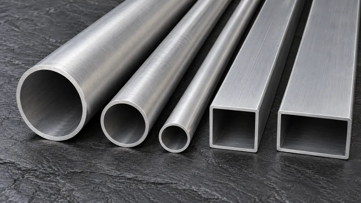
Aluminium oil cooler tube is a thin-wall flat or rectangular tube, usually high-frequency welded from brazing-clad strip, that carries engine oil, transmission fluid or hydraulic oil through a brazed cooler core. Its job is to hold pressure, transfer heat to the fins and braze reliably to headers and turbulators. This guide covers tube types, clad materials, typical sizes, tolerances, brazing and inspection, so you can specify the tube with confidence.
Oil coolers keep engine oil, automatic-transmission fluid, power-steering fluid and hydraulic oil within their working temperature range. Most modern coolers for vehicles and mobile machinery are all-aluminium brazed cores: rows of tubes carrying oil, separated by corrugated fins that carry air or coolant, joined to headers at each end in a single furnace brazing cycle.
The tube is the part that touches the oil, so it carries most of the engineering load. It must provide a defined flow path with an acceptable pressure drop for a viscous fluid; contain the operating pressure plus pressure spikes from cold starts, when thick oil can push pressure far above normal; transfer heat efficiently through a thin wall to the fins; and form a sealed, strong braze joint with fins, headers and any internal turbulator. It must also resist corrosion from the outside environment and keep enough strength after the brazing cycle, which anneals the metal.
Oil is far more viscous than water or refrigerant, and heat transfer on the oil side is usually the limiting factor in the cooler. That is why oil cooler tubes so often contain an inserted turbulator or a dimpled wall: both break up the slow, laminar oil flow near the wall and can raise heat transfer substantially, at the cost of a higher pressure drop.
Large heat-transfer gain; turbulator also stiffens the tube against pressure
Compact, high-duty coolers
Fin height and pitch, oil viscosity, allowable pressure drop, inner cladding
Dimpled tube
Regular dimples pressed into the wall, often touching opposite wall
Turbulence without a separate insert; dimples brazed together add pressure strength
Designs needing simpler assembly with better heat transfer
Dimple depth and pattern, flow area, burst strength
Rectangular heavy-wall tube
Single channel, thicker wall
Robust for high pressure and rough service
Hydraulic coolers on construction and agricultural machinery
Wall thickness, corner radii, weld seam quality
Extruded multi-port tube
Several channels formed in the extrusion
No weld seam; internal webs carry pressure
Some compact and high-pressure designs
Alloy, port shape, corrosion protection
The choice is mainly a trade-off between heat transfer, pressure drop, pressure capacity and cost. Inserted turbulators give the highest performance but need tube strip clad on the inside as well as outside so the insert brazes to the wall. Dimpled tubes avoid the insert and the extra assembly step. Plain tubes remain the low-cost choice where the cooler has enough frontal area.
Clad materials
Core alloys and brazing clad structures
Welded oil cooler tube is roll-formed from brazing sheet: a core alloy carrying the strength, with a thin layer of low-melting aluminium-silicon alloy bonded to one or both faces. During brazing the clad layer melts, flows into the joints by capillary action and freezes to form fillets, while the core stays solid. The clad thickness is expressed as a percentage of total strip thickness, commonly around 5 – 15 % per side.
Clad structure
Character
Typical use
4343 / 3003 / 4343
Double-sided clad; good formability and dependable brazing; inner clad lets turbulators braze to the wall
Automotive engine and transmission oil coolers
4343 / 3003 (single side)
Outer clad only; used where nothing brazes inside the tube
Plain tubes brazed to fins and headers
4045 / 3003 / 4045
Higher-silicon clad gives more fluid filler and larger fillets
Designs needing more filler at joints
4343 / 3005 or modified 3xxx core
Higher post-braze core strength
Heavy-duty truck and construction-machinery coolers
Long-life cores with zinc or interliner layers
Sacrificial layer guides corrosion sideways rather than through the wall
Coolers exposed to road salt or aggressive coolants
Alloy
Role
Key alloying elements (nominal)
Melting behaviour
3003
Core
Mn about 1.0 – 1.5 %, Cu 0.05 – 0.20 %
Melting range about 640 – 655 °C, stays solid during brazing
3005
Core
Mn about 1.0 – 1.5 %, Mg 0.20 – 0.6 %
Stronger than 3003; magnesium content must suit the brazing method
4343
Clad (filler)
Si about 6.8 – 8.2 %
Melts at about 577 – 613 °C, flows at brazing temperature
4045
Clad (filler)
Si about 9.0 – 11.0 %
Melts at about 577 – 591 °C, more fluid than 4343
Composition ranges follow the Aluminum Association registrations; melting ranges are typical published values. Magnesium above a few tenths of a percent interferes with flux (CAB) brazing, so magnesium-bearing cores are matched to vacuum brazing or to suitable fluxes.
Typical sections
Common oil cooler tube sizes
Oil cooler tubes are produced in two broad families: thin-wall flat tubes for compact automotive cores and heavier rectangular tubes for hydraulic and industrial coolers. The tables list sections that are commonly requested. Other widths, heights and walls are made to drawing; a new size usually needs new forming rolls rather than a new die.
Width (mm)
Height (mm)
Wall thickness (mm)
16
4
0.32 / 0.40 / 0.50
19
3.2
0.40
27.66
3.19
0.50
30
4
0.45
32
2
0.30 / 0.50
34.7
3
0.50
43
4.3
0.40 / 0.50
65
4.3
0.40
Thin-wall flat oil cooler tube: typical sections.
Width (mm)
Height (mm)
Wall thickness (mm)
9.9
9.9
1.2
16
12
1.0 / 1.2
20
16
1.2
20
20
1.2
22
40.5
1.5
27
14
1.2
27
19
1.5
30
30
1.2
32
12
1.0
38
19
1.2 / 1.5
45
26
1.5
54.8
16
2.6
Rectangular oil cooler tube: typical sections for heavy-duty and hydraulic coolers.
Tube is supplied in cut lengths for core assembly, or in straight long lengths for the customer to cut. Specify cut length, end condition (square cut, deburred, sized ends) and whether ends must be free of internal burrs, because burrs restrict flow and can trap flux.
Dimensional control
Tolerances and why they matter in production
Characteristic
Typical reference tolerance
Effect in production
Width
About ±0.05 mm
Fit in header slots; too tight jams, too loose leaves gaps the filler cannot bridge
Height
About ±0.05 – 0.06 mm
Core stack height and fin contact
Wall thickness
About ±0.02 mm for thin-wall tube
Pressure capacity, weight and post-braze strength
Crown (bulge of flat faces)
About ±0.10 mm
Contact between tube and fin along the full width
Corner radius / end dimensions
About ±0.05 mm
Header slot fit at the tube ends
Straightness, twist, cut length, burr height, weld position
Agreed on drawing
Automated tube insertion and core flatness
Reference values frequently used for thin-wall welded oil cooler tube; final tolerances are agreed on the customer drawing.
Braze clearance is the most important reason for tight tolerances. Capillary flow of the molten clad works best in a narrow, even gap. If the tube varies in width or height, some joints are starved of filler while others pool it, which leads to leaks or blocked passages. Consistent tube geometry also keeps the core flat after brazing, which matters when the cooler is bolted into a tight space.
Joining
Designing the tube for reliable brazing
Controlled-atmosphere brazing (CAB)
The most common method for automotive coolers. Non-corrosive fluoride flux is applied to the core, which is brazed in a nitrogen atmosphere at a peak of roughly 595 – 610 °C. Works well with 3003 cores and 4343 or 4045 clad.
Vacuum brazing
No flux; magnesium in the clad or core helps break up oxide in vacuum. Common for stacked-plate and bar-and-plate coolers and for magnesium-bearing, higher-strength materials.
Clean surface
Low residual rolling oil and forming lubricant, so flux wets the surface and filler flows evenly. Excess oil leaves carbon and voids in joints.
Continuous weld seam
The HF weld seam must be fully fused, with the inside bead controlled so it does not obstruct turbulator insertion or trap flux.
Even joint gaps
Tube, header slot and fin dimensions are chosen together so gaps stay small and uniform across the core.
Post-braze strength
Brazing anneals the tube, so pressure capacity is calculated from post-braze (O-temper) properties of the core alloy, not its as-supplied strength.
Quality control
How oil cooler tube is inspected
Eddy current testingIn-line eddy current inspection checks the wall and weld seam continuously for cracks, pinholes and incomplete fusion.
Burst testingSample lengths are sealed and pressurised to failure to confirm pressure capacity and weld integrity.
Dimensional measurementVision systems or gauges measure width, height, crown and corner radii against the drawing.
Cross-section examinationProfile projection shows section shape and weld position; etched sections show clad thickness and weld fusion.
Brazing trialSample cores brazed in the customer furnace confirm fillet formation and leak-tightness before volume release.
Ask for dimensional reports, burst test results and the mill test certificate (EN 10204 3.1) with each lot. For new programmes, a production part approval package agreed with your quality team avoids repeated qualification later.
Comparison
Welded, extruded or folded tube: which suits an oil cooler?
Factor
HF welded clad tube
Extruded tube
Folded tube
Source of braze filler
Built into the clad strip
None; filler from clad fins or added flux/filler
Built into the clad strip
Internal turbulator
Easy: insert brazes to inner clad
Not usual; channels formed in extrusion
Internal web formed by folding
Wall thickness range
Very thin to moderate
Moderate; thin webs possible in multi-port
Very thin
Weld seam
Yes, inspected by eddy current
No seam (or die weld lines)
No weld; brazed fold
New size cost
Forming rolls
Extrusion die
Forming rolls
Typical use
Most automotive and machinery oil coolers
Some compact or high-pressure designs
Radiators and condensers more than oil coolers
For most oil coolers, welded clad tube wins because the cladding supplies filler for both the outer fins and the inner turbulator, and wall thickness can be chosen precisely for the pressure. Extruded tube is chosen when a seamless section or integral channels are preferred, and folded tube is more common in radiators and condensers. If you are unsure, send the operating conditions and core design and we will suggest the tube construction that fits.
Applications
Where aluminium oil cooler tubes are used
Engine oil coolers in cars, vans and motorcycles, often integrated with the radiator module
Transmission and gearbox oil coolers, including automatic and dual-clutch transmissions
Heavy trucks and buses, where wider tubes and stronger cores cope with higher heat loads and vibration
Construction, mining and agricultural machinery hydraulic oil coolers, typically using heavier rectangular tubes
Industrial lubrication systems, compressors, wind-turbine gearboxes and hydraulic power units
Power-steering and retarder coolers on commercial vehicles
A typical passenger-car transmission cooler might use 16 × 4 mm double-clad flat tube with a wall near 0.4 mm and an inserted turbulator, while a typical excavator hydraulic cooler uses rectangular tube of around 27 × 19 mm with a 1.5 mm wall, chosen for pressure capacity and resistance to rough service.
Ordering
What to include in an oil cooler tube enquiry
DimensionsWidth, height, wall thickness, corner radii, length and tolerances, or a drawing.
StructurePlain flat tube, dimpled, with turbulator, or a special section.
MaterialCore alloy, clad alloy and clad ratio on each side, and any corrosion requirement.
PerformanceFluid, operating and burst pressure, and brazing method (CAB or vacuum).
CommercialSample quantity, annual volume, destination and delivery terms (EXW, FOB, CIF or DAP).
Tubes are packed in protective cartons or crates that keep thin walls from crushing and keep surfaces clean and dry, with labels for batch traceability.
What material are aluminium oil cooler tubes made from?
Usually brazing sheet with a 3003 or modified 3xxx core and a 4343 or 4045 aluminium-silicon clad layer on one or both sides, roll-formed and high-frequency welded into a flat or rectangular tube.
Why is the tube clad on the inside as well as the outside?
Inner cladding provides filler metal to braze an inserted turbulator or touching dimples to the tube wall. Plain tubes with nothing inside need only outer cladding.
Turbulator or dimpled tube: which is better?
Inserted turbulators usually give higher heat transfer and add pressure strength but cost more and add an assembly step. Dimpled tubes are simpler and cheaper with a smaller heat-transfer gain. The best choice depends on oil viscosity, space and allowable pressure drop.
Can oil cooler tube be made to my drawing?
Yes. Width, height, wall, corner radii, weld position and internal structure can be made to drawing. New sizes usually need new forming rolls, so share the drawing early.
How is aluminum oil cooler tube tested?
In-line eddy current testing of the wall and weld seam, burst tests on samples, dimensional measurement, cross-section examination and, for new programmes, brazing trials in the customer furnace.
Is the tube suitable for vacuum brazing?
Yes, with the right material. Vacuum brazing uses magnesium-bearing clad or core alloys; CAB uses flux and low-magnesium materials. Tell us your process so the clad structure is matched.
Need oil cooler tube for a new cooler programme?
Send the section, clad structure, brazing method and volumes. We will reply with options, certification and delivered terms.