Inside root radius
A fillet at the inner corner (for example R = t on structural angles) reduces stress concentration, improves metal flow and extends die life. Sizes in inch dimensions such as 50.8 × 50.8 × 6.35 mm usually carry R ≈ t.



Every extruded aluminium angle is pushed through a steel die cut to its exact L-shape, so the die decides which sizes are quick and economical to buy. Standard metric angles from 5 × 5 mm to 200 × 200 mm already have tooling in the extrusion supply chain, so they can be ordered without a tooling charge. This guide lists those standard sizes, explains how angle dies are designed, and shows when a custom die is worth it.
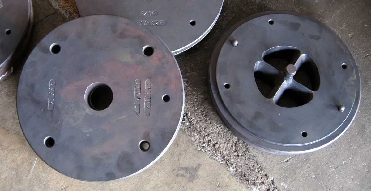
An angle is an open, solid profile: it has no enclosed hollow. That means it is made on a solid die (also called a flat die), a hardened steel disc with an L-shaped aperture machined through it, rather than the more complex porthole or bridge dies used for tubes.
In the press, a billet heated to roughly 450 – 500 °C is forced through the aperture. The metal leaves the die as a continuous angle, is cooled on the run-out table, stretched by a small percentage to straighten it and relieve stress, cut into lengths and aged to temper (T5 or T6). The die itself is supported by a backer and bolster, and is usually made from H13 hot-work tool steel that is hardened and often nitrided to resist wear.
The critical feature inside the die is the bearing: the short land around the aperture that controls the speed of the metal. Thick sections flow faster than thin ones, so the die maker uses longer bearings where the angle is thick (the corner) and shorter bearings at the thin toes. When these are balanced correctly, both legs come out straight, flat and at a true 90°. Poorly balanced dies give twisted angles, wavy toes or an angle that is open or closed beyond tolerance.
The sizes below are commonly tooled metric equal angles. Weights are calculated from the nominal section (2A − t) × t at 2.70 g/cm³ and ignore the small root fillet; use them for estimates.
| Size A × A × t (mm) | Section area (mm²) | Weight (kg/m) |
|---|---|---|
| 5 × 5 × 0.6 | 6 | 0.015 |
| 5 × 5 × 1 | 9 | 0.024 |
| 6 × 6 × 1 | 11 | 0.030 |
| 8 × 8 × 1 | 15 | 0.041 |
| 10 × 10 × 1 | 19 | 0.051 |
| 10 × 10 × 1.5 | 28 | 0.075 |
| 12 × 12 × 1.2 | 27 | 0.074 |
| 12 × 12 × 1.5 | 34 | 0.091 |
| 15 × 15 × 1.2 | 35 | 0.093 |
| 15 × 15 × 1.5 | 43 | 0.115 |
| 16 × 16 × 1.4 | 43 | 0.116 |
| 18 × 18 × 1.5 | 52 | 0.140 |
| 19 × 19 × 1.5 | 55 | 0.148 |
| 20 × 20 × 1.5 | 58 | 0.156 |
| 20 × 20 × 2 | 76 | 0.205 |
| 25 × 25 × 1.5 | 73 | 0.196 |
| 25 × 25 × 2 | 96 | 0.259 |
| 25 × 25 × 3 | 141 | 0.381 |
| 28 × 28 × 2.5 | 134 | 0.361 |
| 30 × 30 × 2 | 116 | 0.313 |
| 30 × 30 × 3 | 171 | 0.462 |
| 30 × 30 × 4 | 224 | 0.605 |
| 32 × 32 × 3 | 183 | 0.494 |
| 35 × 35 × 3 | 201 | 0.543 |
| 38 × 38 × 3 | 219 | 0.591 |
| 38 × 38 × 4 | 288 | 0.778 |
| 40 × 40 × 3 | 231 | 0.624 |
| 40 × 40 × 4 | 304 | 0.821 |
| 40 × 40 × 5 | 375 | 1.012 |
| 45 × 45 × 3 | 261 | 0.705 |
| 45 × 45 × 4 | 344 | 0.929 |
| 50 × 50 × 3 | 291 | 0.786 |
| 50 × 50 × 4 | 384 | 1.037 |
| 50 × 50 × 5 | 475 | 1.282 |
| 50 × 50 × 6 | 564 | 1.523 |
| 55 × 55 × 5 | 525 | 1.417 |
| 60 × 60 × 4 | 464 | 1.253 |
| 60 × 60 × 5 | 575 | 1.552 |
| 60 × 60 × 6 | 684 | 1.847 |
| 63 × 63 × 5 | 605 | 1.634 |
| 63 × 63 × 6 | 720 | 1.944 |
| 65 × 65 × 6 | 744 | 2.009 |
| 70 × 70 × 6 | 804 | 2.171 |
| 70 × 70 × 7 | 931 | 2.514 |
| 75 × 75 × 6 | 864 | 2.333 |
| 75 × 75 × 8 | 1136 | 3.067 |
| 80 × 80 × 6 | 924 | 2.495 |
| 80 × 80 × 8 | 1216 | 3.283 |
| 90 × 90 × 6 | 1044 | 2.819 |
| 90 × 90 × 8 | 1376 | 3.715 |
| 100 × 100 × 8 | 1536 | 4.147 |
| 100 × 100 × 10 | 1900 | 5.130 |
| 110 × 110 × 10 | 2100 | 5.670 |
| 120 × 120 × 10 | 2300 | 6.210 |
| 120 × 120 × 12 | 2736 | 7.387 |
| 130 × 130 × 10 | 2500 | 6.750 |
| 150 × 150 × 10 | 2900 | 7.830 |
| 150 × 150 × 12 | 3456 | 9.331 |
| 150 × 150 × 15 | 4275 | 11.543 |
| 160 × 160 × 12 | 3696 | 9.979 |
| 180 × 180 × 15 | 5175 | 13.973 |
| 200 × 200 × 16 | 6144 | 16.589 |
Inch-based equal angles (for example 1 × 1 × 1/8 in, 2 × 2 × 1/4 in or 4 × 4 × 3/8 in) also have widely available tooling, both as structural angle with root radius and as sharp-corner architectural angle. See the aluminium angle bar guide for inch sizes and weights.
| Size A × B × t (mm) | Section area (mm²) | Weight (kg/m) |
|---|---|---|
| 15 × 20 × 1.2 | 41 | 0.110 |
| 20 × 25 × 1.5 | 65 | 0.176 |
| 20 × 30 × 2 | 96 | 0.259 |
| 20 × 38 × 2 | 112 | 0.302 |
| 25 × 30 × 2 | 106 | 0.286 |
| 25 × 30 × 3 | 156 | 0.421 |
| 25 × 38 × 2 | 122 | 0.329 |
| 30 × 40 × 2 | 136 | 0.367 |
| 30 × 40 × 3 | 201 | 0.543 |
| 30 × 45 × 3 | 216 | 0.583 |
| 35 × 45 × 3 | 231 | 0.624 |
| 40 × 50 × 3 | 261 | 0.705 |
| 40 × 50 × 4 | 344 | 0.929 |
| 40 × 60 × 3 | 291 | 0.786 |
| 40 × 60 × 4 | 384 | 1.037 |
| 45 × 70 × 4 | 444 | 1.199 |
| 50 × 65 × 4 | 444 | 1.199 |
| 50 × 75 × 5 | 600 | 1.620 |
| 56 × 70 × 5 | 605 | 1.634 |
| 60 × 80 × 5 | 675 | 1.823 |
| 60 × 80 × 6 | 804 | 2.171 |
| 70 × 90 × 6 | 924 | 2.495 |
| 75 × 100 × 8 | 1336 | 3.607 |
| 80 × 100 × 8 | 1376 | 3.715 |
| 90 × 110 × 8 | 1536 | 4.147 |
| 100 × 120 × 8 | 1696 | 4.579 |
| 100 × 150 × 10 | 2400 | 6.480 |
| 120 × 150 × 10 | 2600 | 7.020 |
| 120 × 160 × 12 | 3216 | 8.683 |
Unequal angles with very long, thin legs, such as 100 × 20 × 1.8 mm or 150 × 50 × 8 mm, also exist as standard tooling in many markets, usually with small root radii. They are useful as edge trims and panel seats where one leg is hidden and the other forms a visible return.
A fillet at the inner corner (for example R = t on structural angles) reduces stress concentration, improves metal flow and extends die life. Sizes in inch dimensions such as 50.8 × 50.8 × 6.35 mm usually carry R ≈ t.
A radius on the outer heel for safety on edge guards and handrails, or to match a design language. Adds a second radius to specify.
A return lip on one or both toes increases stiffness of the free edge and creates a seat for panels or gaskets. Needs a custom die but is still a solid profile.
A thickened, rounded toe raises the section modulus with little extra weight; common in marine stiffeners.
Angles at 60°, 100°, 120° or 135° for faceted enclosures and cladding. The die is simple, but tolerances on the included angle must be agreed.
Different leg thicknesses, grooves for screws or serrations for grip. Every extra feature adds die complexity, so keep only the features you need.
Angles are among the easiest shapes to extrude, but a few limits decide whether a profile is practical and economical:
| Parameter | Practical guidance | Why it matters |
|---|---|---|
| Circumscribing circle (CCD) | Most presses handle angles up to about 200 – 300 mm CCD economically; larger needs big presses | Die size, press size and cost all scale with CCD |
| Minimum wall | Around 0.6 – 1.0 mm for small 6060/6063 angles; 1.5 – 3 mm for 6061/6082 or larger CCDs | Thin walls need lower speeds and are harder to keep flat |
| Leg-to-thickness ratio | Up to roughly 20 – 30:1 for 6063; lower for harder alloys | Very thin long legs wave and twist on the run-out table |
| Thickness variation | Keep adjacent thickness ratios below about 2 – 3:1 | Uneven sections cool and flow unevenly, causing distortion |
| Corner radii | Add a small radius (0.5 – 1 mm minimum) to every corner | Sharp internal corners crack dies and concentrate stress |
| Included angle | State the nominal angle and tolerance on the drawing | Open/closed angle is a common rejection cause |
These are general industry guidelines. The extruder's die designer confirms final limits for each alloy, press and profile.
Alloy matters too. 6060 and 6063 flow easily and suit thin, sharp, decorative angles. 6061 and 6082 are stiffer to push, so they need slightly thicker walls and generous radii. 7075 and 2024 angles are extruded at much lower speeds, which is why they cost more and why fewer die sizes exist for them.
Under these standards the allowed deviation grows with the size of the section and its CCD. For buyers, the points that cause most problems are the included angle (squareness), twist over the length, and straightness of the toes. If an angle will be used as a precision stop, a datum or a visible trim, call out tighter tolerances on the drawing, and ask for the inspection method to be agreed before production.
A new die is justified when a standard size does not meet the function, when a lip, groove or radius saves later machining, or when the annual volume is large enough that a lighter, optimised section saves more in metal than the die costs. Extrusion dies are relatively low-cost tooling compared with casting or stamping tools, so even modest volumes can justify them.
Metline supplies standard and custom angle extrusions in all common alloys to fabricators and project buyers worldwide, with cutting and finishing on request.
Usually not. Standard metric and inch angle sizes are already tooled across the extrusion industry, so you pay only for the metal, extrusion and any finishing or cutting. A tooling charge applies only when a new die must be made.
A solid (flat) die, because an angle has no hollow. It is machined from hardened H13 hot-work tool steel, with bearing lengths adjusted so the thick corner and thin toes leave the die at the same speed.
Small 6063 trim angles around 5 × 5 × 0.6 mm are routinely extruded. Below that, metal flow and handling become difficult and roll-formed strip may be a better route.
Yes, but harder alloys need thicker walls, larger radii and slower extrusion. Expect fewer standard sizes and a higher price per kilogram in 7075 than in 6063 or 6061.
Die life depends on alloy, section and press conditions. Dies are routinely nitrided and refurbished to extend their life, and a worn die is replaced as part of normal tooling maintenance rather than charged to each order.
Leg lengths, thickness of each leg, root and toe radii, included angle, tolerances, alloy and temper, finish, visible faces and the expected annual volume.
Send your size list or drawing with alloy, finish, quantity and destination, and we will confirm the tooling route and quote.






