Surface cleanliness
Residual rolling oil or particles create weak spots in the dielectric and raise dissipation factor. Foil must be annealed clean and stored dry.



Capacitor foil is thin aluminium used as the electrodes of capacitors. Film and paper capacitors use plain foil about 4.5 – 10 µm thick in 1050, 1060, 1100 or 1235, while electrolytic capacitors use etched high-purity anode foil and thinner cathode foil. Metline supplies plain capacitor foil and high-purity foil stock in slit rolls to capacitor and electrode makers worldwide.
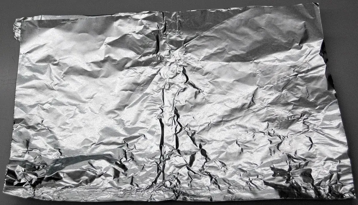
Every capacitor stores charge on two conducting plates separated by a dielectric. In wound capacitors those plates are long ribbons of aluminium foil rolled up with the dielectric between them. Aluminium is used because it conducts well, rolls to a few micrometres without pinholes, and, in electrolytic types, grows its own insulating oxide film.
| Capacitor type | Role of the foil | Typical foil |
|---|---|---|
| Film / foil capacitor | Plain foil electrodes wound with polypropylene or polyester film | 1050, 1060, 1235, 1100 in O temper, about 4.8 – 10 µm |
| Paper and oil-impregnated power capacitor | Plain foil electrodes wound with capacitor paper or film | Similar plain foil, often 5 – 7 µm |
| Aluminium electrolytic – anode | Etched to multiply surface area, then anodised to form the Al2O3 dielectric | Purity 99.9 – 99.99 %+, roughly 70 – 130 µm; high cubic texture for high-voltage foil |
| Aluminium electrolytic – cathode | Etched foil that contacts the electrolyte | Commercial purity or Al-Mn / Al-Cu alloy, roughly 20 – 50 µm |
Metallised film capacitors replace foil with a vacuum-deposited aluminium layer only nanometres thick; foil electrodes are still chosen where high pulse current or high RMS current makes a solid foil conductor the safer option.
| Alloy | Aluminium, min | Main limits (max, %) | Typical capacitor use |
|---|---|---|---|
| 1050 | 99.50 % | Si 0.25, Fe 0.40, Cu 0.05 | Plain electrode foil, cathode foil base |
| 1060 | 99.60 % | Si 0.25, Fe 0.35, Cu 0.05 | Plain foil where slightly higher conductivity is wanted |
| 1100 | 99.00 % | Si + Fe 0.95, Cu 0.05 – 0.20 | General foil with a little more strength |
| 1235 | 99.35 % | Si + Fe 0.65, Cu 0.05 | The most common thin-gauge foil alloy; good pinhole performance |
| High-purity (1A99 / 99.99 %) | 99.99 % | Very low Fe, Si and Cu | Electrolytic anode foil before etching |
For plain electrode foil, low iron and silicon reduce intermetallic particles that cause pinholes and breaks at very thin gauges. For anode foil, purity and crystal orientation control how evenly the etching tunnels form, which sets the capacitance per square centimetre.
| Thickness (inches) | Thickness (mm) | Thickness (µm) | Approx. weight (g/m²) |
|---|---|---|---|
| 0.00019 | 0.0048 | 4.8 | 13.0 |
| 0.00020 | 0.0051 | 5.1 | 13.8 |
| 0.00025 | 0.0064 | 6.4 | 17.3 |
| 0.00030 | 0.0076 | 7.6 | 20.5 |
| 0.00035 | 0.0089 | 8.9 | 24.0 |
| 0.00040 | 0.0102 | 10.2 | 27.5 |
Residual rolling oil or particles create weak spots in the dielectric and raise dissipation factor. Foil must be annealed clean and stored dry.
At 5 – 7 µm a pinhole becomes a potential breakdown path. Alloy cleanliness and rolling practice control the count.
Even gauge gives even capacitance along the winding and consistent roll diameter.
Telescoping or loose rolls cause misalignment in the capacitor element. Rolls must be wound flat with controlled tension.
Burrs can pierce thin film and short the electrodes; edge quality is checked on each roll.
Tensile strength and elongation must suit high-speed winding without breaks.
| Standard | Scope |
|---|---|
| ASTM B479 | Annealed aluminium and aluminium-alloy foil for flexible barrier and other applications |
| EN 546 (parts 1 – 4) | Aluminium foil: delivery conditions, mechanical properties, tolerances and surface requirements |
| JIS H4160 | Aluminium and aluminium alloy foils |
| IEC 60384-1 | Fixed capacitors for electronic equipment: generic specification |
| IEC 60384-4 | Sectional specification for aluminium electrolytic capacitors |
Plain electrode foil for film and paper capacitors is usually about 4.8 – 10 µm. Electrolytic anode foil is much thicker, roughly 70 – 130 µm before etching, and cathode foil about 20 – 50 µm.
Plain foil is rolled from 1235, 1050, 1060 or 1100. Electrolytic anode foil needs high-purity aluminium of 99.9 – 99.99 % or more so that etching and forming give a uniform dielectric.
Etching dissolves microscopic tunnels into the foil, multiplying its surface area many times. Since capacitance scales with area, etched foil stores far more charge per square centimetre than smooth foil.
Foil capacitors use separate aluminium foil electrodes and handle high pulse currents well. Metallised film capacitors use an aluminium layer vacuum-deposited on the film, which is smaller and self-healing but carries less peak current.
Yes. Metline ships slit capacitor foil rolls worldwide in sealed, moisture-protected packing with mill certificates.
Tell us the alloy, gauge, width and core. We will confirm availability, certification and a delivered price.






